Protection shield positioning assembly and positioning device therefor and method of use

Active Publication Date: 2007-08-16
FEDERAL MOGUL WORLD WIDE LLC
View PDF26 Cites 43 Cited by
  • Summary
  • Abstract
  • Description
  • Claims
  • Application Information

AI Technical Summary

Benefits of technology

[0007] The invention concerns a positioning device for holding a first elongated member at a predetermined position along a second elongated member. The second elongated member is positioned within a bore extending through the first elongated member. The positioning device comprises a band surrounding a central space. At least one flexible, resilient finger is attached to the band. Each finger has a first end attached to the band and a second end that extends radially inwardly into the central space. At least one of the second ends is engageable with the second elongated member received within the central s

Problems solved by technology

Due to the nature of the protective sleeve and its environment, it is difficult to attach the sleeve to the sensor in a manner which will allow the sleeve to be reliably secured in a desired position and also be readily removable for installation and servicing of the sensor.
Adhesives, tape and frictional fits are used to effect attachment, but these

Method used


Image

  • Protection shield positioning assembly and positioning device therefor and method of use
  • Protection shield positioning assembly and positioning device therefor and method of use
  • Protection shield positioning assembly and positioning device therefor and method of use

Examples


embodiment 33

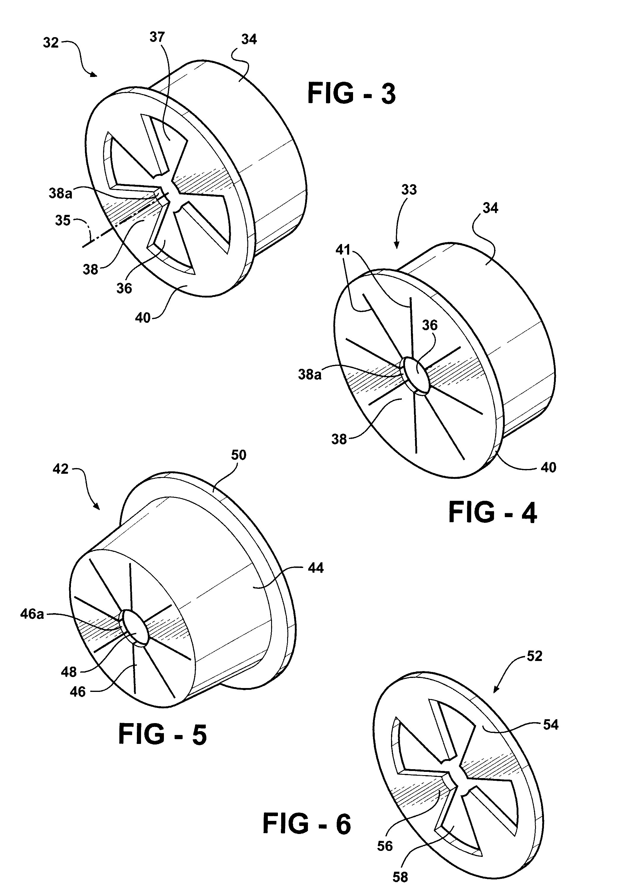
[0032]FIG. 4 shows an alternate embodiment 33 of the positioning device, substantially similar to device 32 but, wherein the fingers 38 are positioned adjacent to one another, and thus, substantially omits the spaces between the adjacent fingers 38. Instead, the adjacent fingers 38 are spaced circumferentially from one another by slits 41 having a generally uniform width along their length.

first embodiment

[0033]FIG. 5 shows another alternate embodiment 42 of the positioning device. The positioning device 42 comprises an elongated, tapered band 44 to which are attached a plurality of fingers 46. The band 44 defines a central space 48 into which the fingers 46 extend. The fingers 46 are arranged circumferentially around the band 44 adjacent to one another (alternately, they may be in spaced apart relation as in the first embodiment above). Preferably, the ends 46a of fingers 46 are shaped (in this case with a circular arc) to accommodate the elongated item that they will engage during use. A rim 50 extends radially outwardly from the band 44, wherein the rim 50 is positioned at an opposite end of band 44 from the fingers 46.

[0034]FIG. 6 illustrates another alternate embodiment 52 of the positioning device. Again, the device 52 comprises a band 54 to which a plurality of resilient, flexible fingers 56 are attached. The band 54 is not elongated as in the embodiments previously described ...


PUM

PropertyMeasurementUnit
Lengthaaaaaaaaaa
Electrical resistanceaaaaaaaaaa
Flexibilityaaaaaaaaaa

Abstract

A method and assembly for protecting a device connected to a wiring harness is disclosed. The assembly includes a protective shield having a bore for receiving the device and a positioning device. An elongated wiring harness extends from the device being protected and through the bore of the protective shield. The positioning device is formed having a band that surrounds a central space. At least one flexible, resilient finger extends radially inwardly from the band into the central space. At least one of the fingers forcibly engages the harness sleeve to maintain the positioning device and the protective shield in a predetermined protection position along the harness sleeve at least partially surrounding the device being protected.

Description

CROSS-REFERENCE TO CO-PENDING APPLICATION [0001] This application is a continuation-in-part of prior U.S. application Ser. No. 10 / 942,651, filed on Sep. 16, 2004, which is incorporated herein by reference in its entirety.BACKGROUND OF THE INVENTION [0002] 1. Technical Field [0003] This invention concerns a device for positioning and maintaining a protective sleeve or other elongated item at a predetermined position covering a sensor or other object. [0004] 2. Related Art [0005] Sensors used in automotive applications, such as oxygen sensors which provide data to control engine operation and performance, are often mounted within the engine compartment of a vehicle where they are subject to a harsh environment including intense radiant heat, sources of abrasion and constant vibration during vehicle operation. In view of the harsh environment, it is advantageous to cover the relatively delicate sensors with protective sleeving which can damp vibration, protect against abrasion and refl...

Claims


Application Information

Patent Timeline
IPC IPC(8): A61F13/20
CPCB60R16/0222Y10T29/49879H02G3/0691F16L57/04H02G3/0418H02G3/0468B60R16/02F16B2/22H02G15/013H02G15/043H02G15/04B60R16/023F16L3/13G01D11/245
Inventor SELLIS, TIMOTHY D.HARRIS, DAVID A.UPTON, KENNETH C.WINTERS, DANNY E.FRYBERGER, SAMUEL B. JR.
Owner FEDERAL MOGUL WORLD WIDE LLC
Why Eureka
Try Eureka