
Aerodynamic structures for tractor to trailer junction

a technology of aerodynamic structure and tractor, which is applied in the direction of roofs, transportation and packaging, vehicle arrangements, etc., can solve the problems of tractor and trailer, create aerodynamic drag, and net pressure differen

Inactive Publication Date: 2007-08-30
ARCONIC INC
View PDF17 Cites 69 Cited by
  • Summary
  • Abstract
  • Description
  • Claims
  • Application Information

AI Technical Summary

Benefits of technology

[0007] In one embodiment, the air shield arrangement may provide a tractor cab extension. In one embodiment, the tractor cab extension includes two side panel assemblies, which may also be referred to as deflectors, installed to each sidewall of the tractor cab. Each of the sidewall assemblies include hinge connected front and rear panels, wherein the front panel may be hinge connected to the tractor cab at of the edge defined by the intersection of the sidewall to the rear face of the tractor cab. In one embodiment, the device also includes a lever that

Problems solved by technology

One disadvantage, however, is that there is a gap between the tractor and trailer that creates aerodynamic drag.
The gap between the tractor and trailer tends to trap air creating a low-pressure wake behind the tractor, resulting in a net pressure difference and, therefore, creating drag.

Method used


Image

  • Aerodynamic structures for tractor to trailer junction
  • Aerodynamic structures for tractor to trailer junction
  • Aerodynamic structures for tractor to trailer junction

Examples


Embodiment Construction

[0025] Detailed embodiments of the present invention are disclosed herein; however, it is to be understood that the disclosed embodiments are merely illustrative of the invention that may be embodied in various forms. In addition, each of the examples given in connection with the various embodiments of the invention are intended to be illustrative, and not restrictive. Further, the figures are not necessarily to scale, some features may be exaggerated to show details of particular components. Therefore, specific structural and functional details disclosed herein are not to be interpreted as limiting, but merely as a representative basis for teaching one skilled in the art to variously employ the present invention.

[0026] For the purposes of the description hereinafter, the terms “upper”, “lower”, “front”, “rear”, “top” and “bottom”, and derivatives thereof shall relate to the invention, as orientated in the embodiments depicted in the figures.

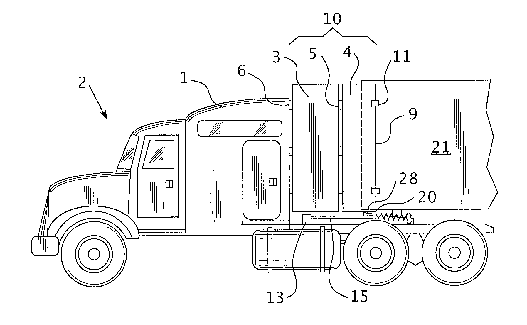
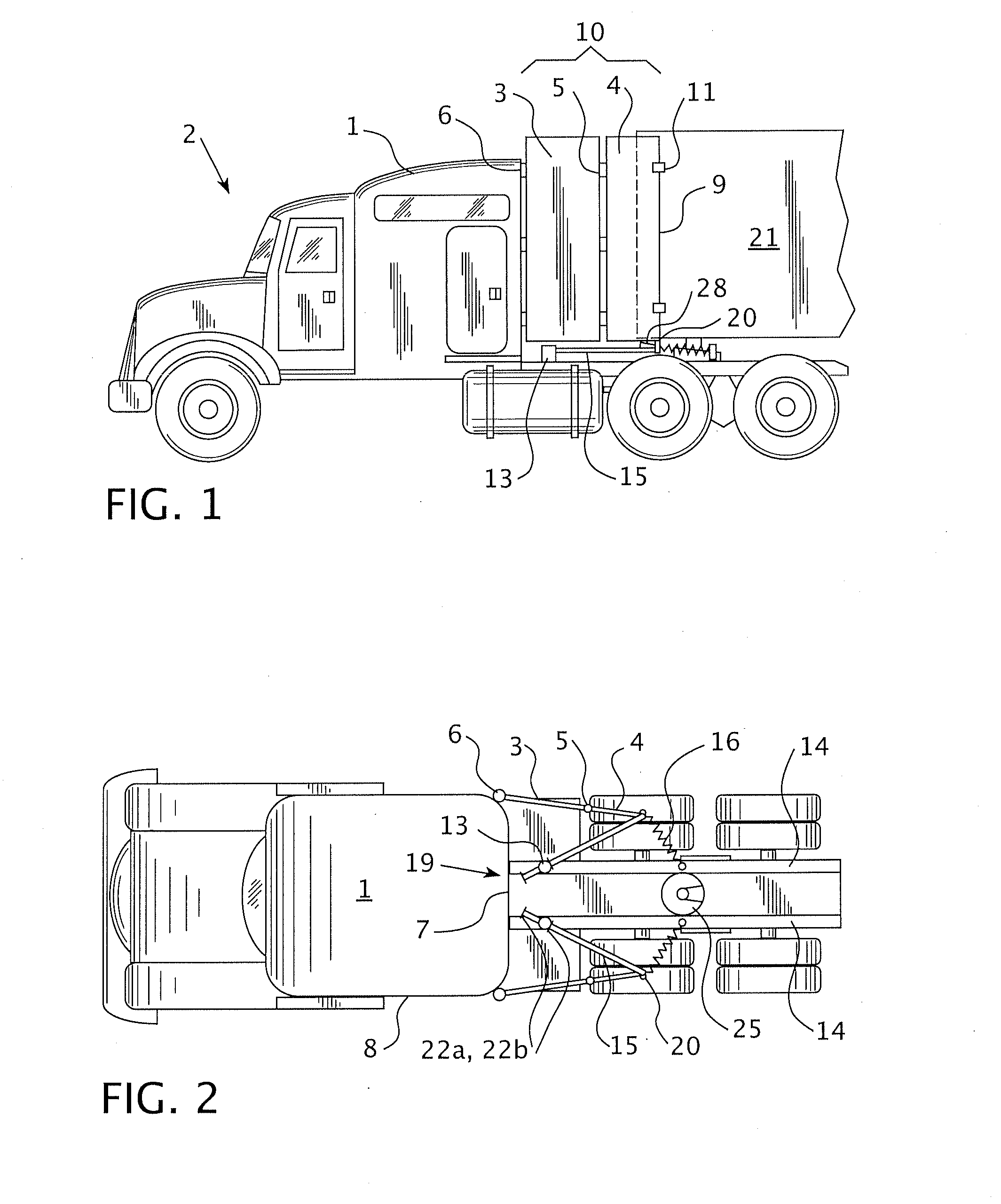
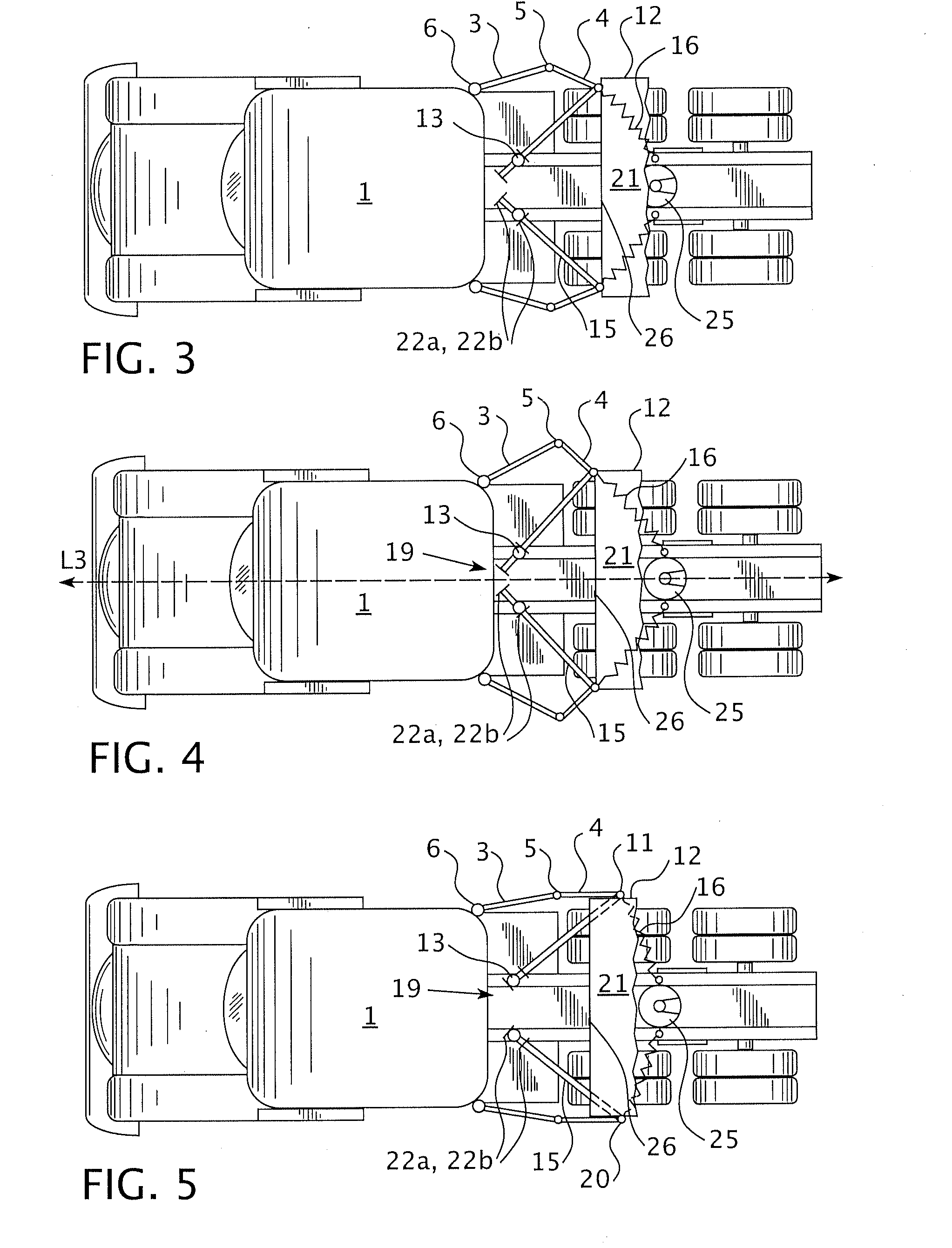
[0027] Referring to FIGS. 1-3, in one e...


PUM


Abstract

The present invention provides an air shield comprising side panel assemblies in hinged connection to each rear edge of a sidewall of a tractor and an actuation assembly including a boss in rotational engagement to the frame of the tractor and between a cab and a fifth wheel of the tractor, a lever having an adjustable length engaged to the boss at a first end and engaged to side panel assembly at a second end, and a spring including a first end connected to the side panel assembly and a second end connected to the frame of the tractor between the boss and the rear of the trailer frame.

Description

CROSS REFERENCE TO RELATED APPLICATION [0001] The present invention claims the benefit of U.S. provisional patent application 60 / 764,082 filed on Jan. 31, 2006, the whole contents and disclosure of which is incorporated by reference and also claims the benefit of U.S. provisional patent application 60 / 764,078 filed on Jan. 31, 2006, the whole contents and disclosure of which is incorporated by reference as is fully set forth herein.FIELD OF THE INVENTION [0002] The present invention is related to structures and arrangements that in one embodiment reduces aerodynamic drag in moving vehicles. BACKGROUND OF THE INVENTION [0003] The semi-trailer truck (tractor) and junction to a trailer, as used for hauling cargo, has advantages over the conventional straight trucks in that it can carry a greater cargo and is more adaptable for steering in close quarters. One disadvantage, however, is that there is a gap between the tractor and trailer that creates aerodynamic drag. The gap between the ...

Claims


Application Information

Patent Timeline
IPC IPC(8): B62D35/00
CPCB62D35/001B62D33/0612
Inventor LOTAREV, ALEXEY ANATOLIEVICHLOGATCHEV, DMITRY NIKOLAYEVICHYAZEV, MAXIM NIKOLAYEVICHVASIL'YEV, VLADIMIR PETROVICHMEDVEDEV, ALEXANDER VITALIYEVICHABASHKIN, VASILIY GENNADIEVICHMALININ, LEONID
Owner ARCONIC INC
Features
  • Generate Ideas
  • Intellectual Property
  • Life Sciences
  • Materials
  • Tech Scout
  • Unparalleled Data Quality
  • Higher Quality Content
  • 60% Fewer Hallucinations
Learn More