Stent-graft having flexible geometries and methods of producing the same

a stent-graft and flexible technology, applied in the field of flexible stent-graft devices and methods, can solve the problems of plastic deformation of expanded polytetrafluoroethylene grafts, prone to leakage of blood through stent-graft endoprosthesis, physical deformation, etc., and achieve different bending flexibility, different bending flexibility, and increased bending flexibility

Inactive Publication Date: 2007-09-06
LIFESHIELD SCI
View PDF36 Cites 52 Cited by
  • Summary
  • Abstract
  • Description
  • Claims
  • Application Information

AI Technical Summary

Benefits of technology

[0026] In another aspect of the present invention, a method of making a stent-graft having increased bending flexibility is provided. The method of this aspect of the present invention includes the steps of providing a radially distensible, tubular stent including opposed open ends and a stent wall structure having opposed exterior and luminal surfaces; providing a continuously uninterrupted and optionally seamless ePTFE tubular graft having a node and fibril structure securably disposed to at least one of the stent surfaces, the graft including a tubular wall substantially free of slits, apertures and folds, the graft further including a first region and a second region; and providing the first region with a different bending flexibility from the second region. Desirably, the step of providing the f

Problems solved by technology

Expanded polytetrafluoroethylene grafts, however, are subject to plastic deformation, especially when, for example, compressing the stent-graft for loading into its delivery system, delivering the stent-graft through a highly tortuous bodily lumen and/or placing or deploying the stent-graft at the target implant site.
Such plastic deformation may lead to the tearing of the ePTFE, leaving the stent-graft endoprosthesis prone to leakage of blood therethrough.
Furthermore, plastic deformation of expanded polytetrafluoroethylene grafts may lead to physical deformities in the graft, such as buckling, which is also undesirable because it may lead to poor blood flow patterns.
Such stent-grafts having a unitary tubular ePTFE covering adhesively secured to the stent, however, do not have differential flexibility associated with the graft to augment bending or plastic deformation

Method used


Image

  • Stent-graft having flexible geometries and methods of producing the same
  • Stent-graft having flexible geometries and methods of producing the same
  • Stent-graft having flexible geometries and methods of producing the same

Examples


Embodiment Construction

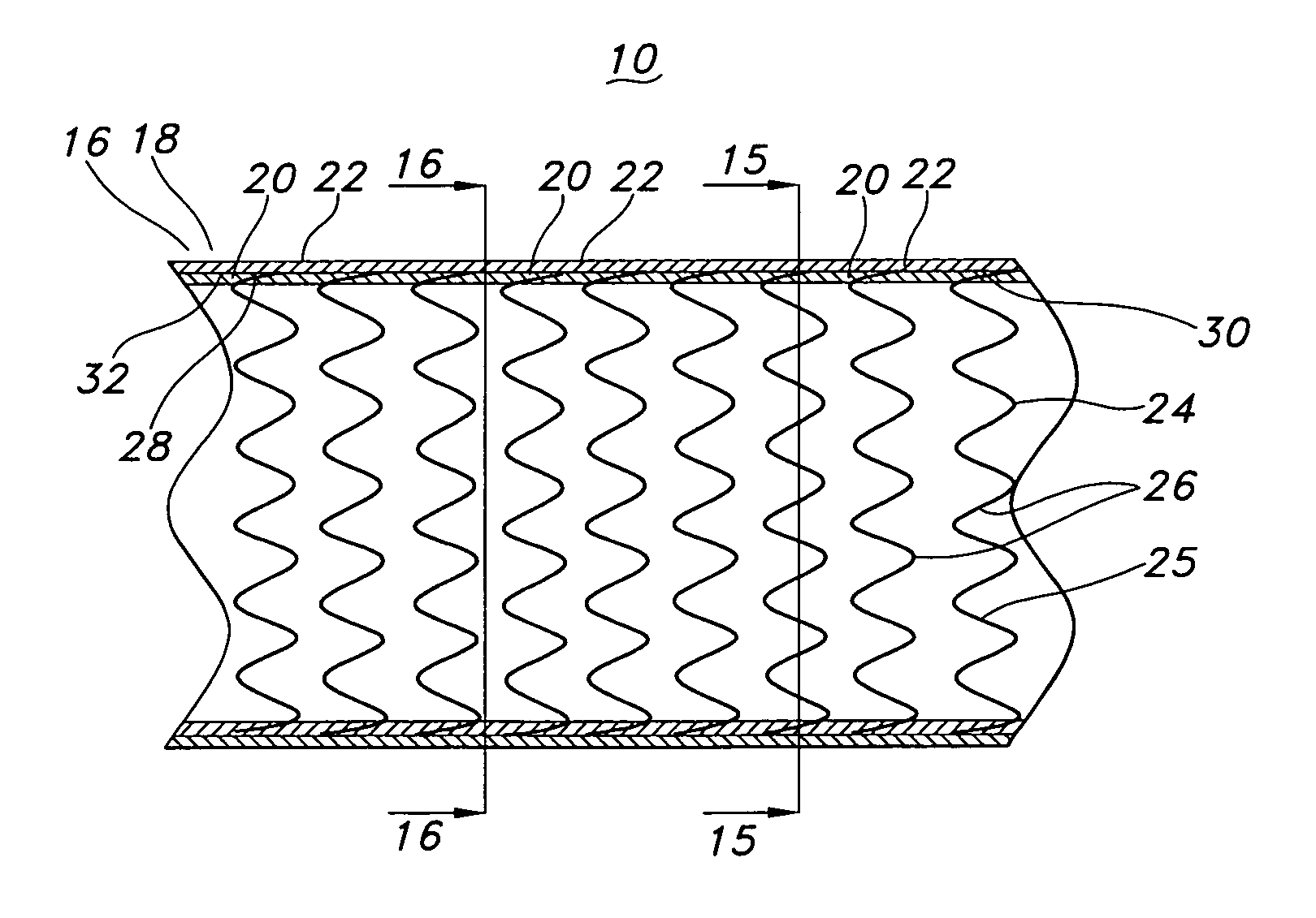
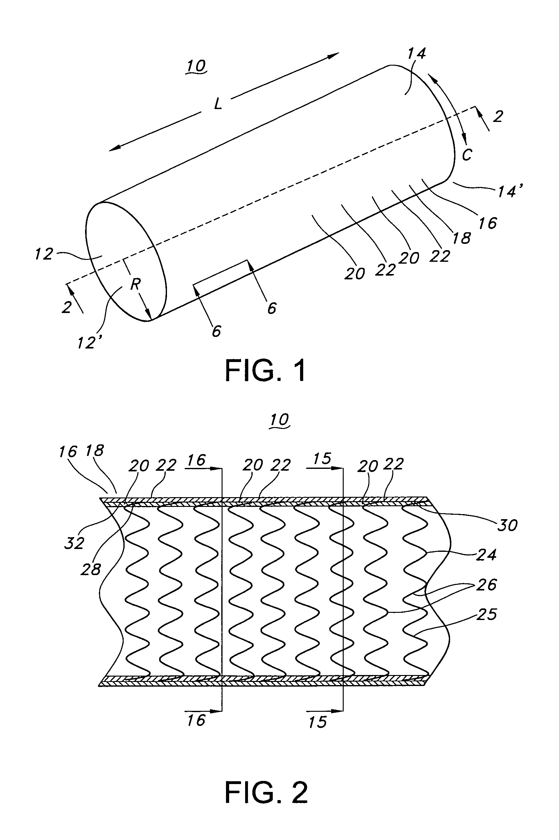
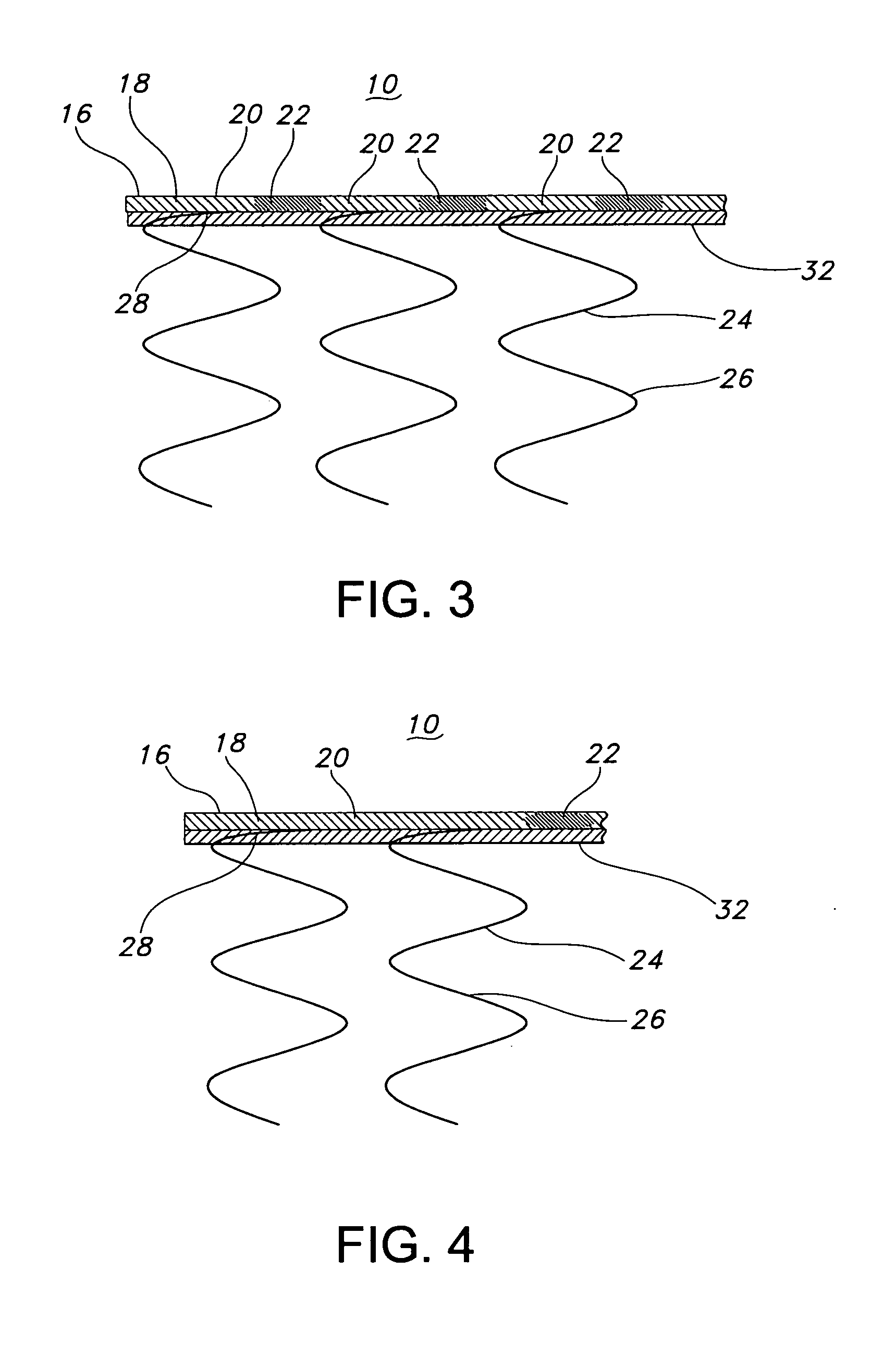
[0048]FIG. 1 is a perspective view of a stent-graft 10 having enhanced flexibility of the present invention. The stent-graft 10 is a hollow, tubular structure or device having opposed open ends 12, 14. The stent-graft 10 includes a tubular wall 16 disposed between the open ends 12, 14. As depicted in FIG. 1, the tubular wall 16 extends along the longitudinal direction, which is depicted as the L-axis, of the stent-graft 10. The tubular wall 16 includes a graft 18 having plurality graft portions or regions 20, 22 that, as described below, have varied or different flexibilities, such as bending flexibilities. The graft wall 16 also extends around the circumference, which is indicated by the C-axis or C-vector, of the stent-graft 10. The R-axis defines a radial extent of the stent-graft 10 of the present invention. As depicted in FIG. 1, stent-graft 10 is a substantially longitudinally straight tubular device, but the present invention is not so limited. Stent-graft 10 may have a varyi...


PUM


Abstract

A stent-graft or prosthesis (10) with enhanced flexibility, in particular enhanced bending flexibility, includes a radially distensible stent (24) and at least one continuously uninterrupted ePTFE tubular graft or covering (18) having a node and fibril structure. The tubular stent (24) includes opposed open ends (12′, 14′) and a stent wall structure (26) having opposed exterior (28) and luminal surfaces (30). The ePTFE covering (18) is securably disposed to at least one of the stent surfaces (28, 30). The ePTFE graft or covering (18) includes a tubular wall (16) that is continuously uninterrupted and desirably substantially free of slits, apertures and folds. The ePTFE graft (18) further includes a first region (20) and a second region (22), where the first region (20) has a different bending flexibility from the second region (22).

Description

FIELD OF THE INVENTION [0001] The present invention relates to flexible stent-graft devices and methods for making the same. More particularly, the present invention relates to a radially distensible stent and a non-textile polymeric tubular structure having a plurality of graft regions that differentially bend or plastically deform upon application of a bending stress. BACKGROUND OF THE INVENTION [0002] An intraluminal prosthesis is a medical device used in the treatment of diseased bodily lumens. One type of intraluminal prosthesis used in the repair and / or treatment of diseases in various body vessels is a stent. A stent is generally a longitudinal tubular device formed of biocompatible material which is useful to open and support various lumens in the body. For example, stents may be used in the vascular system, urogenital tract, esophageal tract, tracheal / bronchial tubes and bile duct, as well as in a variety of other applications in the body. These devices are implanted within...

Claims


Application Information

Patent Timeline
IPC IPC(8): A61F2/06
CPCA61F2/07A61F2002/072A61F2002/075A61F2/915A61F2250/0029A61F2/89A61F2/90A61F2250/0028
Inventor QUIGLEY, FERGUS
Owner LIFESHIELD SCI
Why Eureka
Try Eureka