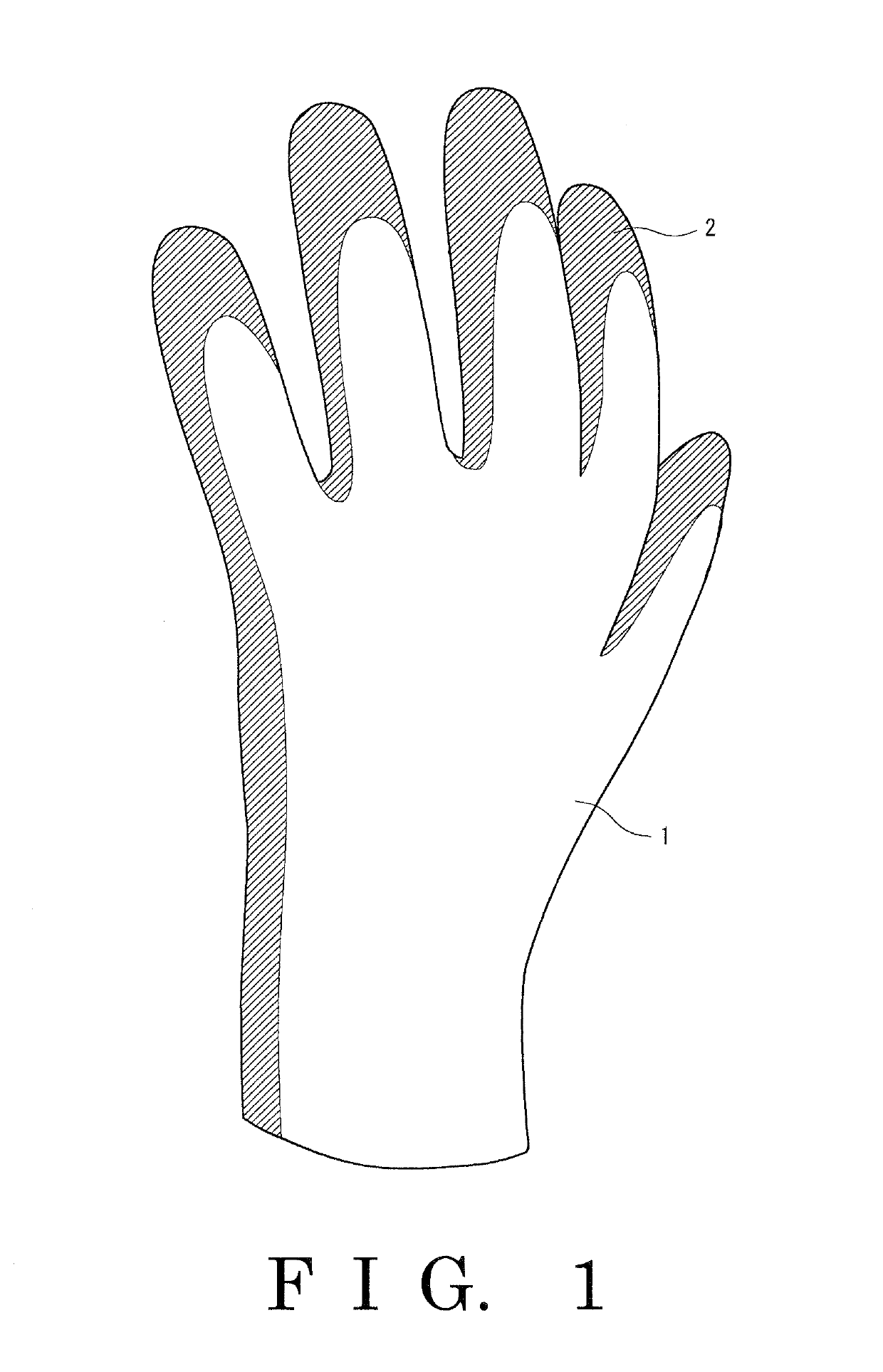
Glove

a glove and bending technology, applied in the field of gloves, can solve the problems of inferior bending flexibility, rigidity, and deterioration of the anti-slipping effect, and achieve the effects of superior heat retention property, superior anti-slipping effect, and superior bending flexibility

Active Publication Date: 2019-07-16
SHOWA GLOVE
View PDF13 Cites 5 Cited by
  • Summary
  • Abstract
  • Description
  • Claims
  • Application Information

AI Technical Summary

Benefits of technology

[0020]As explained in the foregoing, according to the glove of the aspect of the present invention, the glove body is produced using a loop yarn, and irregularities arising from the loop yarn are provided on the surface of the coating layer. Thus, the glove exhibits a superior anti-slipping effect, and achieves both superior bending flexibility and a superior heat-retaining property.

Problems solved by technology

Moreover, the conventional coating layers may be hardly deformed in accordance with an object to be gripped and thus may have inferior followability, leading to a failure to achieve a sufficient anti-slipping effect.
Furthermore, the conventional anti-slipping coating layers have a disadvantage that a part of the coating layer is likely to be detached together with the anti-slipping particles, leading to the deterioration of the anti-slipping effect.
In addition, when the pile fabric faces outside, the glove may exhibit inferior bending flexibility and be rigid due to a short average distance between loops on the outer surface and the presence of a large number of loops.
Furthermore, there is a disadvantage that an inferior heat-retaining property is provided due to the absence of the loop on the inner surface which is to be brought into contact with a hand skin.

Method used


Image

  • Glove
  • Glove
  • Glove

Examples


examples

[0060]Hereinafter, the invention will be explained in more detail by way of Examples, but the invention is not anyhow limited to the following Examples.

[0061]Nine types of glove bodies and three types of compounds each described below were used to produce gloves.

[0062]Each glove body used is as shown in Table 1 below. The glove bodies shown below were not subjected to nap-raising.

[0063]

TABLE 1TotalOuterDistanceKnittingfinenessKnittingdiameter ofbetween loopsmachine(dtex)yarnloops (mm)(mm)Details of yarnsA13 G524loop yarn33core yarn: 33 dtex-polyurethaneelastic fiber covered with single78 dtex-24F woolly nylon;float yarn: acrylic spun 1 / 28; andpresser yarn: single 56 dtex-17Fwoolly nylonB13 G500loop yarn33core yarn: 33 dtex-polyurethaneelastic fiber covered with single78 dtex-24F woolly nylon;float yarn: double woolly nylon166 dtex-48F; andpresser yarn: single 56 dtex-17Fwoolly nylonC13 G556loop yarn33core yarn: 33 dtex-polyurethaneelastic fiber covered with single58 dtex-17F woolly ...

examples 1 to 6

[0067]In Examples 1 to 6, test production was made using the compound of the blend 1 for each of the glove bodies A, B, C, D, E and F under the aforementioned test production condition.

examples 7 to 12

[0068]In Examples 7 to 12, test production was made using the compound of the blend 2 for each of the glove bodies A, B, C, D, E and F under the aforementioned test production condition.


PUM


Abstract

A glove includes: a glove body made of fibers, the glove body being for covering a hand of a wearer; and a coating layer made of a resin or rubber, the coating layer being overlaid at least on a palm region of the outer surface of the glove body, in which a loop yarn is used as a knitting yarn of the glove body, and irregularities arising from the loop yarn are provided on the surface of the coating layer. The ten-point mean roughness (Rz) of the surface of the coating layer is preferably no less than 300 μm and no greater than 1,200 μm. The average outer diameter of loops of the loop yarn is preferably no less than 1 mm and no greater than 6 mm. The average distance between loops of the loop yarn is preferably no less than 1 mm and no greater than 10 mm.

Description

TECHNICAL FIELD[0001]The present invention relates to a glove.BACKGROUND OF THE INVENTION[0002]Gloves are used by workers who wear them in packing works, carrying works and the like at factories, etc., for example. As the gloves of this kind, gloves including a glove body made of fibers, and a coating layer made of a resin or rubber overlaid thereon for imparting an anti-slipping effect are publicly known.[0003]Some conventional coating layers are made from rubber, etc., into which anti-slipping particles are incorporated through kneading; however, the surface of the conventional coating layers has a ten-point mean roughness (Rz) of 40 μm to 90 μm, indicating comparatively small irregularities. Moreover, the conventional coating layers may be hardly deformed in accordance with an object to be gripped and thus may have inferior followability, leading to a failure to achieve a sufficient anti-slipping effect. Furthermore, the conventional anti-slipping coating layers have a disadvanta...

Claims


Application Information

Patent Timeline
Patent Type & Authority Patents(United States)
IPC IPC(8): A41D19/00A41D19/015
CPCA41D19/01547A41D19/01558A41D2500/10D02G3/34D10B2501/041
Inventor KISHIHARA, HIDETOSHI
Owner SHOWA GLOVE
Why Eureka
Try Eureka