Drainage device and methods

a technology of a draining device and a gill, which is applied in the field of gills, can solve the problems of inability to control the lowering of iop and adjust it after surgery using conventional gills, failure of devices, and most contemporary gills not achieving the required iop level. , to achieve the effect of reducing or preventing sideways/lateral movement and/or rotation, improving pressure distribution, and reducing or preventing sideways

Pending Publication Date: 2021-06-03
UCL BUSINESS PLC
View PDF0 Cites 5 Cited by
  • Summary
  • Abstract
  • Description
  • Claims
  • Application Information

AI Technical Summary

Benefits of technology

[0021]The aspect ratio of the cross-section shape at the outer surface may provide particular advantages including, but not limited to, reducing or preventing sideways / lateral movement and / or rotation or twisting of the tube around its longitudinal axis. The aspect ratio of the cross-section shape at the outer surface can also provide improved pressure distribution as the pressure of the tube on surrounding tissues and cells in the patient's eye is distributed across the width of the tube and hence over a larger area than would be the case with a round tube of a similar volume.
[0022]The tube may be anisotropic in bending about two axes each perpendicular to the longitudinal axis. The tube may have a width and a height, and the plurality of lumen may be spaced in the width dimension, and the tube may have a greater bending flexibility in a plane including the height dimension than in a plane including the width dimension. The tube may be malleable in one direction and stiff in another.

Problems solved by technology

Additionally, the ability to control the lowering of IOP and to adjust it after surgery using conventional GDDs is poor.
Most contemporary GDDs do not achieve the lower level of IOP required to minimise glaucomatous progression.
However, if there is too much fibrosis the devices will fail.
Equally, if there is too little fibrosis there is a risk of post-operative hypotony.

Method used


Image

  • Drainage device and methods
  • Drainage device and methods
  • Drainage device and methods

Examples


Embodiment Construction

)

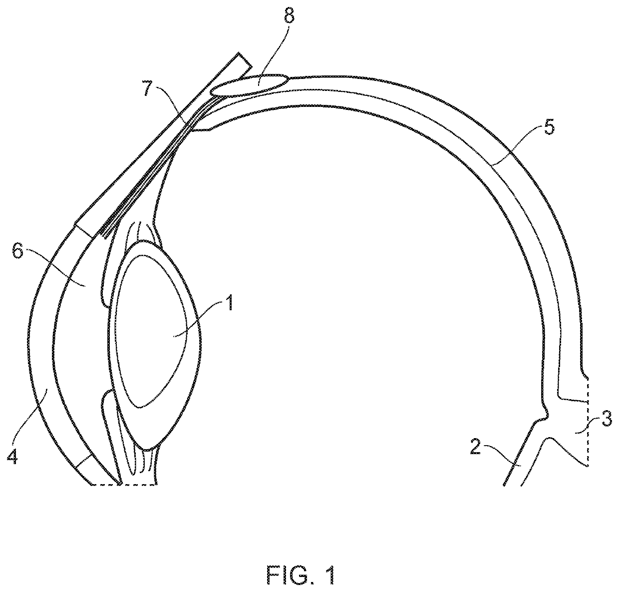
[0084]FIG. 1 illustrates schematically an eye, e.g. of a human, showing the lens 1, retina 2, optic nerve 3, cornea 4, sclera 5 and anterior chamber 6. A glaucoma drainage device (GDD) 7 is used to fluidly connect the anterior chamber 6 to a bleb 8 in the subconjunctival space following trabeculectomy so as to lower the intra-ocular pressure (IOP). The GDD 7 in accordance with a first embodiment is shown in detail in FIGS. 2 to 9.

Shape of the Device

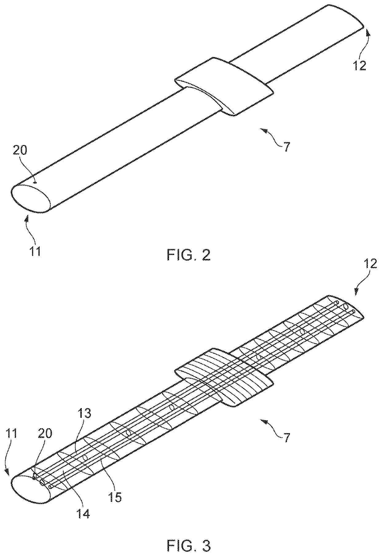
[0085]As shown in FIG. 2, the GDD 7 is a triple-lumen tube having a first end 11 and a second end 12 opposite the first end. FIG. 3 is an ‘X-ray’ type image showing three lumens 13, 14, 15 extending from the first end to the second end. When in use, the first end 11 is for locating in the anterior chamber 6 and the second end is for locating in the subconjunctival space to discharge aqueous humour into the bleb 8.

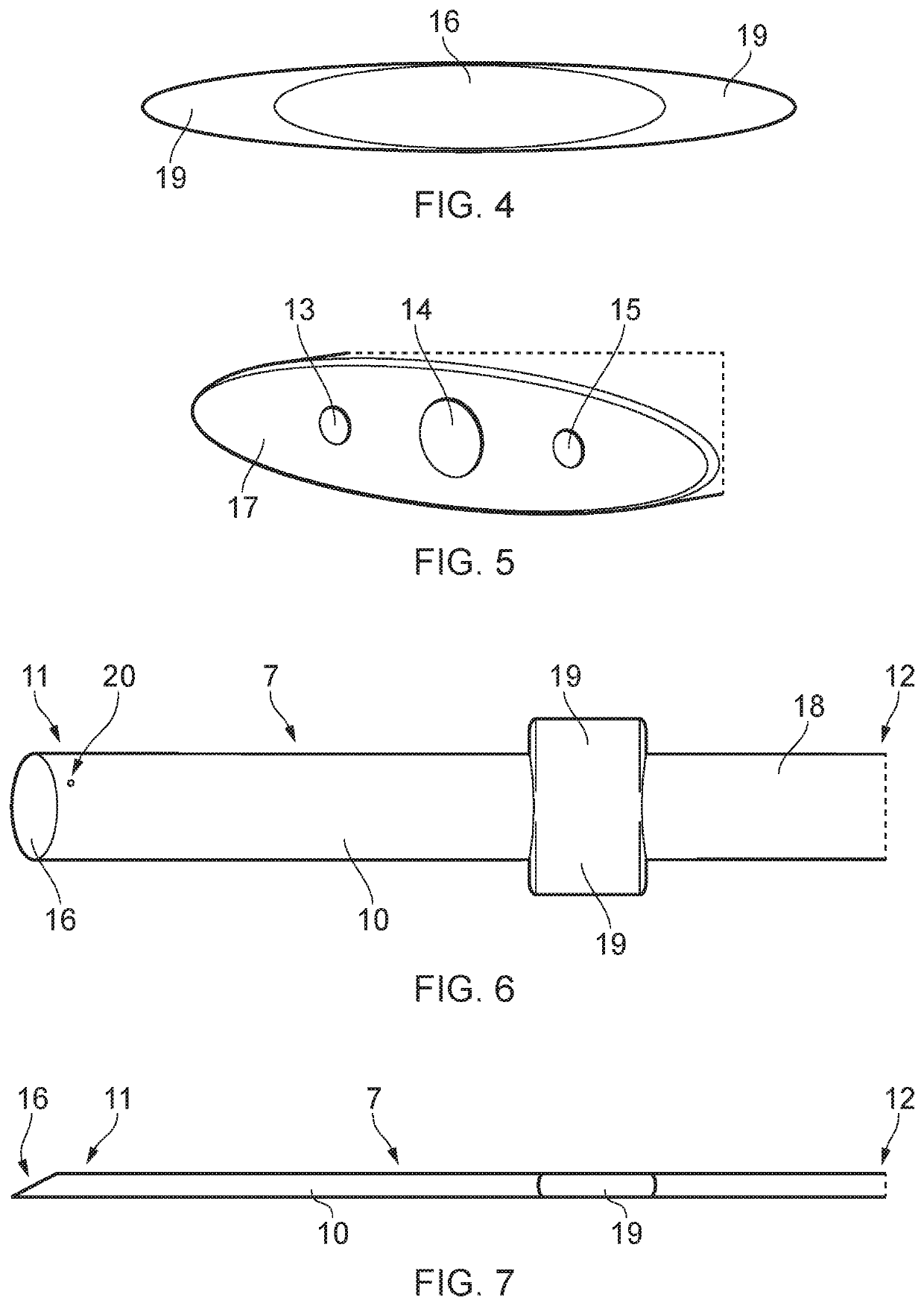
[0086]The tube has a first end face 16 at the first end 11, and a second end face 17 at the second end 12. As best shown in FI...


PUM

PropertyMeasurementUnit
aspect ratioaaaaaaaaaa
diameteraaaaaaaaaa
diameteraaaaaaaaaa

Abstract

A drainage device for use in an eye to drain aqueous humour so as to reduce intraocular pressure or for treating glaucoma. The device has a multi-lumen tube having a first end, a second end opposite the first end, and a plurality of lumen extending between the first end and the second end. At least one of the lumen is sealed at the first end. A flow through the multi-lumen tube is adjusted by forming at least one aperture open in one of the lumen through a wall of the tube and/or sealing at least one aperture open in one of the lumen. The tube has a longitudinal axis through the first end and the second end, and an outer surface extending between the first end and the second end. A cross-section perpendicular to the longitudinal axis has a non-circular shape at the outer surface with an aspect ratio of at least 3:1.

Description

FIELD OF THE INVENTION[0001]The present invention relates to a drainage device and methods for use in the treatment of glaucoma.BACKGROUND OF THE INVENTION[0002]Glaucoma is an irreversible chronic optic neuropathy with characteristic optic nerve head changes and visual field defects. In the eye aqueous fluid is produced by the ciliary body and reaches the anterior chamber formed between the iris and the cornea through the pupil. In a normal eye, the aqueous is removed through the trabecular meshwork. There the aqueous passes through Schlemm's canal and through veins which merge with blood-carrying veins and into venous circulation. Intraocular pressure is maintained in the eye by the intricate balance of secretion and absorption or outflow of the aqueous in the manner described above. Glaucoma results from excessive build-up of aqueous fluid in the anterior chamber producing an increase in intraocular pressure (IOP), which is the major modifiable risk factor associated with glaucoma...

Claims


Application Information

Patent Timeline
Patent Type & Authority Applications(United States)
IPC IPC(8): A61F9/007B29C48/11B29C48/00B23K26/38
CPCA61F9/00781B29C48/11B29C48/0022B29L2031/7546A61F2240/001A61F2230/0008A61F2250/0091B23K26/38
Inventor BOUREMEL, YANNKHAW, PENG TEE
Owner UCL BUSINESS PLC
Why Eureka
Try Eureka