Manufacturing optical elements

a technology of optical elements and mechanical elements, which is applied in the field of manufacturing miniature optical or mechanical elements, can solve the problems of residual material, difficult and costly control of small volumes of dispensed liquid or viscous material, and impair the function of the combined structure,

Inactive Publication Date: 2007-09-20
HEPTAGON
View PDF18 Cites 19 Cited by
  • Summary
  • Abstract
  • Description
  • Claims
  • Application Information

AI Technical Summary

Benefits of technology

[0040] Such means for confining the replication material, or flow confining features are constituted by the inner edge, the buffer volume, the outer edge, the spacer and the inclined spacer; each of them alone, or several of them in combination. They may be combined to form a “multi-tiered” flow con...

Problems solved by technology

However, small volumes of dispensed liquid or viscous material are generally difficult and costly to control.
However, there might be areas sideward of the element where replication material is not wanted in later replication steps.
In certain applications, the fabricated elements must, for exa...

Method used


Image

  • Manufacturing optical elements
  • Manufacturing optical elements
  • Manufacturing optical elements

Examples


Embodiment Construction

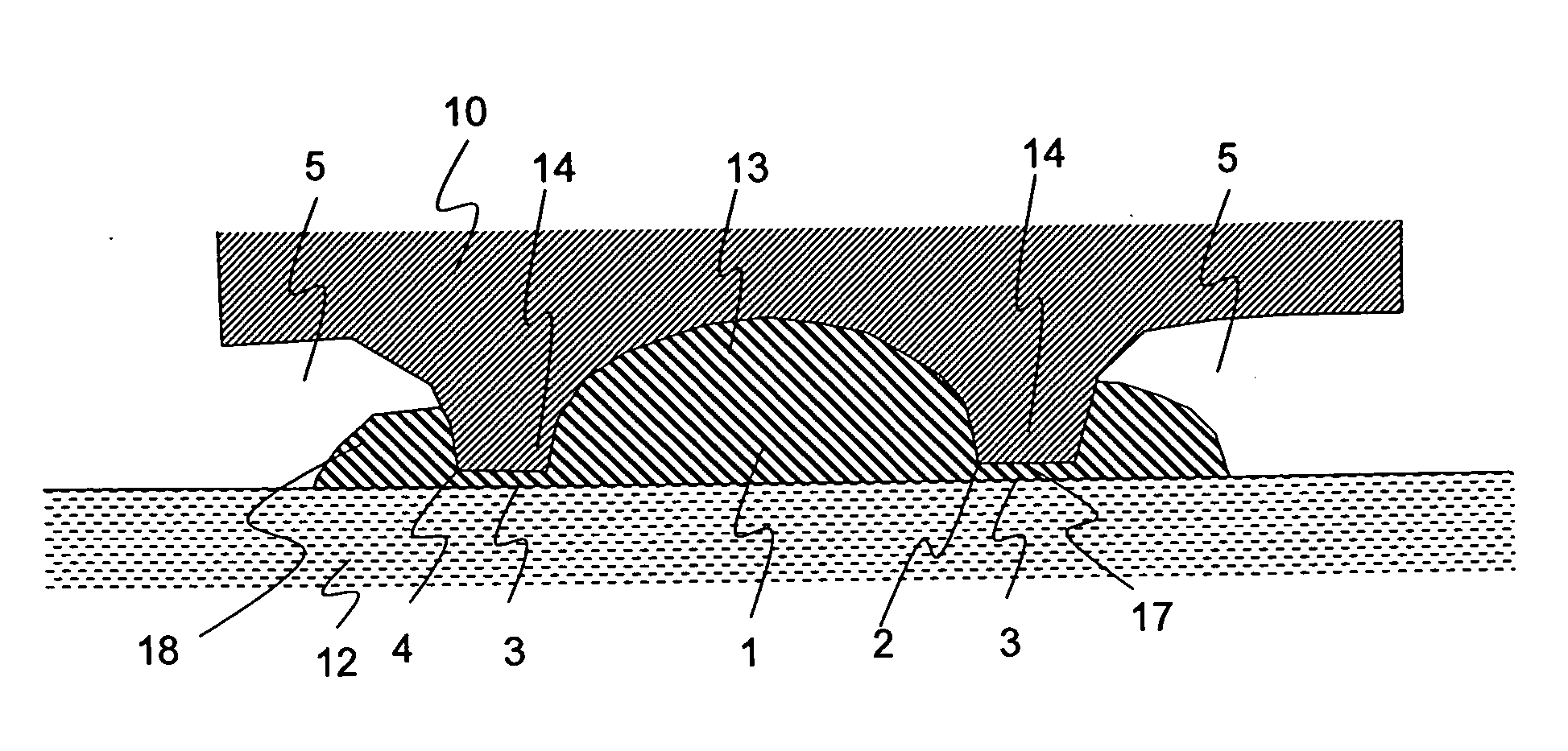
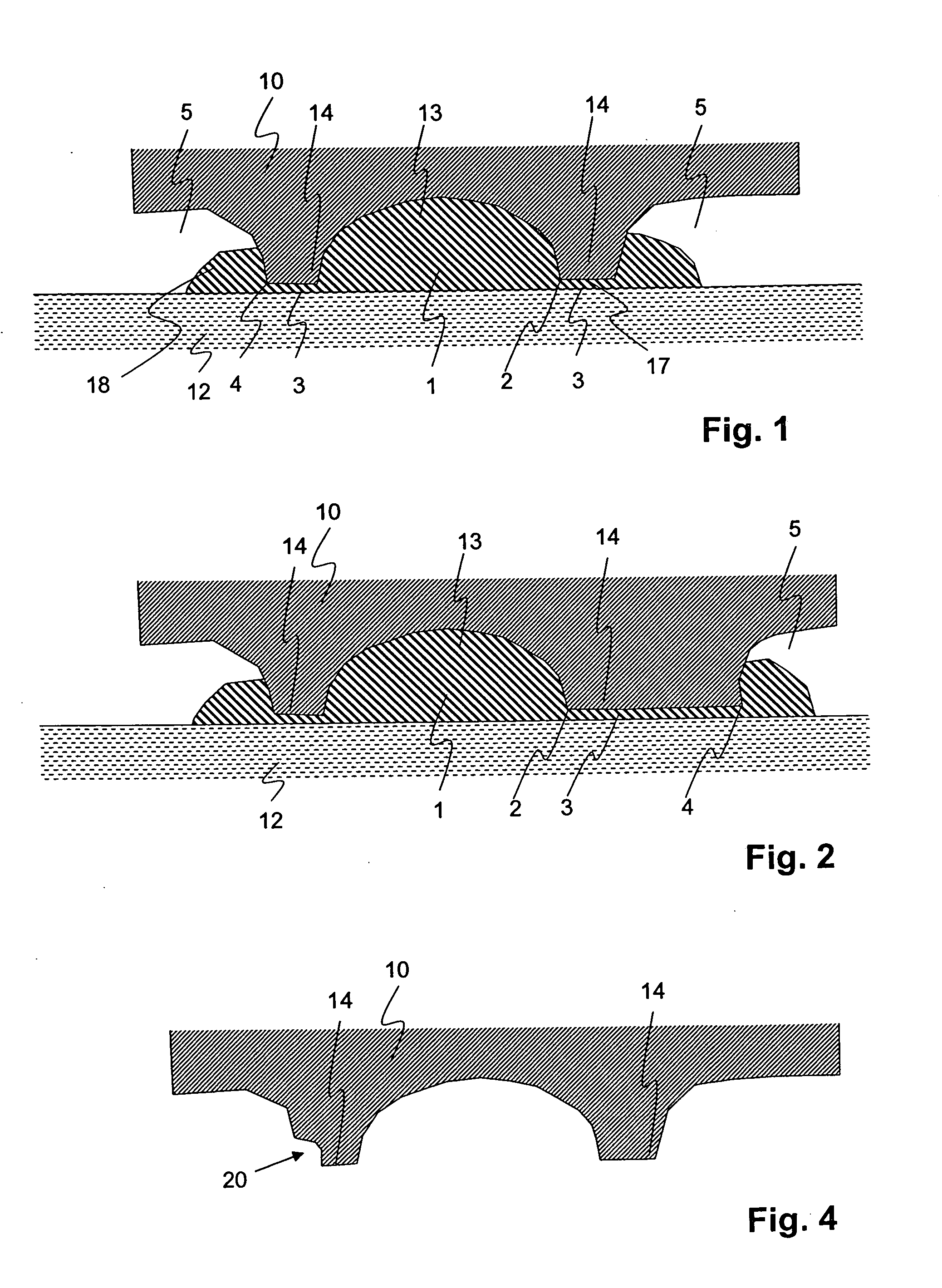
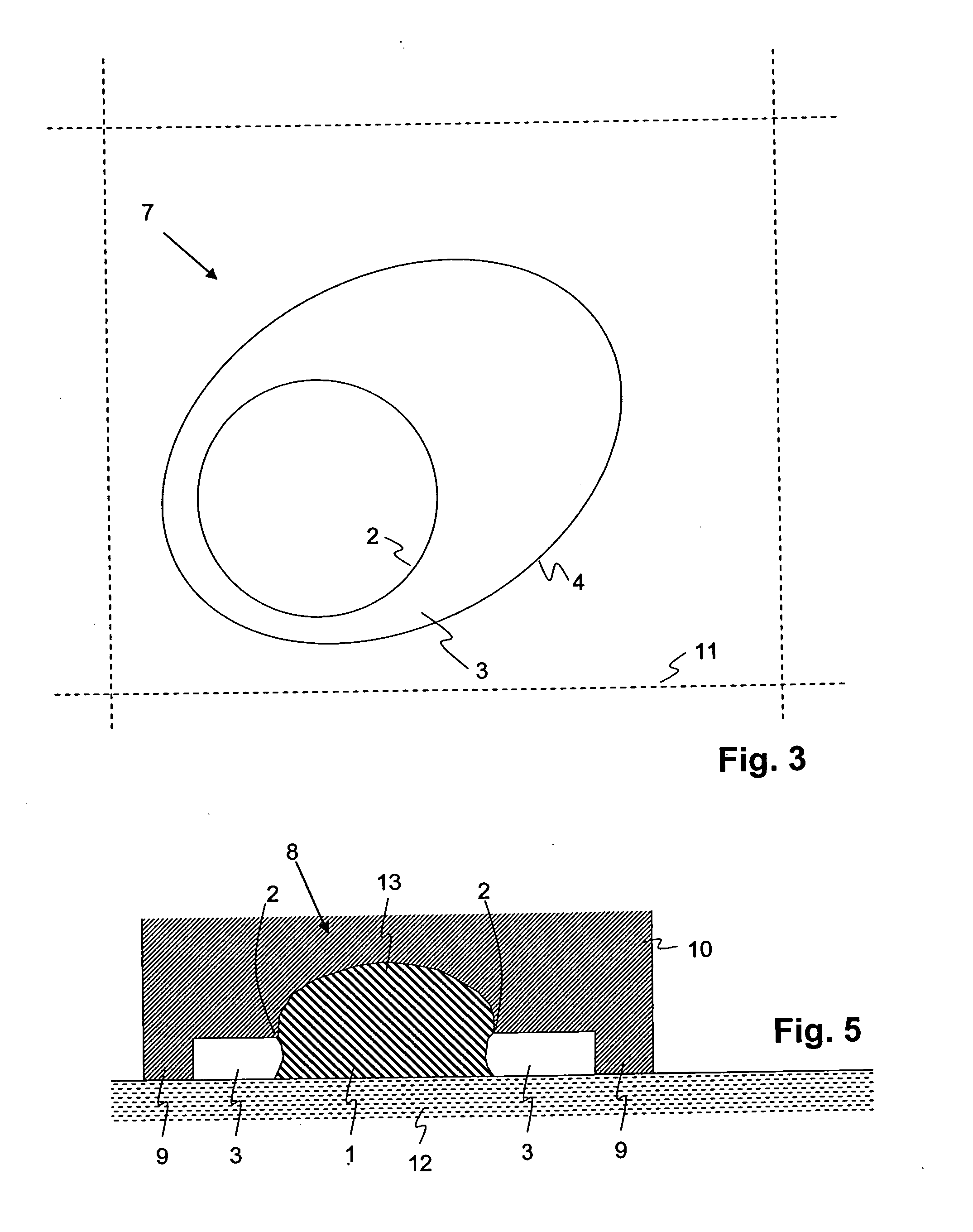
[0057]FIG. 1 schematically shows a cross section through a tool 10 placed on a substrate 12. The tool 10 forms a cavity 8 that defines the shape of the element to be formed by an element volume 1. In the shown case, the optical element is simply a refractive lens. The element volume 1 lies between the tool 10 and the substrate 12. It is surrounded by a protruding element of the tool 10 which here is denoted as a floating spacer 14. A flat surface 17 of the spacer runs approximately parallel to the surface of the substrate 12 and here is at a distance of about 5 μm to 15 μm therefrom. Underneath the floating spacer 14, between the flat surface 17 and the substrate 12, a small buffer volume 3 forms. Between the element volume 1 and the buffer volume 3, the tool 10 comprises an inner edge 2. Between the buffer volume 3 and an overflow volume 5, the tool 10 comprises an outer edge 4.

[0058] The main function of the floating spacer 14 is to pull out excess material by capillary forces. T...


PUM

PropertyMeasurementUnit
Forceaaaaaaaaaa
Flow rateaaaaaaaaaa
Volumeaaaaaaaaaa

Abstract

A method of manufacturing an element using a replication tool, including the steps of providing a replication tool that defines the shape of the element; providing a substrate; pressing the tool against the substrate, with a replication material located between the tool and the substrate; confining the replication material to a predetermined area of the substrate, which predetermined area exceeds the desired area of the element on covering the substrate, in at least one direction along the surface of the substrate by less than a predetermined distance.; hardening (e.g. curing) the replication material to form the element.

Description

BACKGROUND OF THE INVENTION [0001] 1. Field of the Invention [0002] The invention is in the field of manufacturing miniature optical or mechanical elements, in particular refractive optical elements or diffractive micro-optical elements, by means of a replication process that includes embossing or molding steps. More concretely, it deals with a method of replicating an optical element and a replication tool therefore. [0003] 2. Description of the Related Art [0004] Replicated optical elements include diffractive and / or refractive micro-optical elements for influencing an optical beam in any pre-defined manner, refractive elements such as lenses, potentially at least partially reflecting elements etc. [0005] When optical elements are produced by replication, there is often a basic configuration involving a substrate and replication material on a surface thereof, which replication material is shaped and hardened in the course of a replication process. Often, the dimension perpendicula...

Claims


Application Information

Patent Timeline
IPC IPC(8): B29D11/00
CPCB29C43/021B29C43/36Y10S425/808B29D11/00365B29L2011/0016B29C2043/3652B29D11/00307B29D11/0048B29C43/02B29D11/00
Inventor RUDMANN, HARTMUTHEIMGARTNER, STEPHANWESTENHOFER, SUSANNEROSSI, MARKUS
Owner HEPTAGON
Why Eureka
Try Eureka