

Airbag device for vehicle
- Summary
- Abstract
- Description
- Claims
- Application Information
AI Technical Summary
Benefits of technology
Problems solved by technology
Method used
Image

Examples
first embodiment
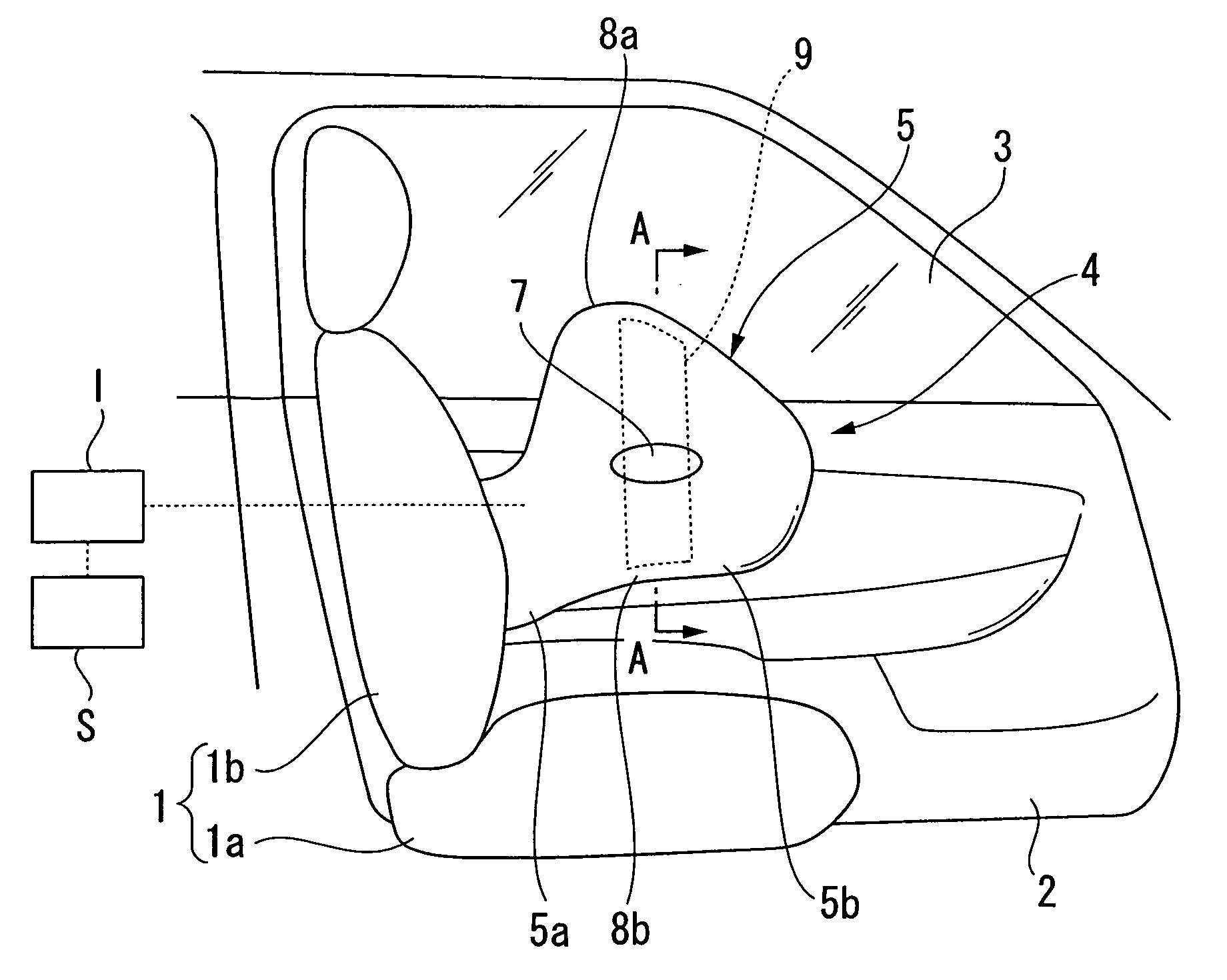
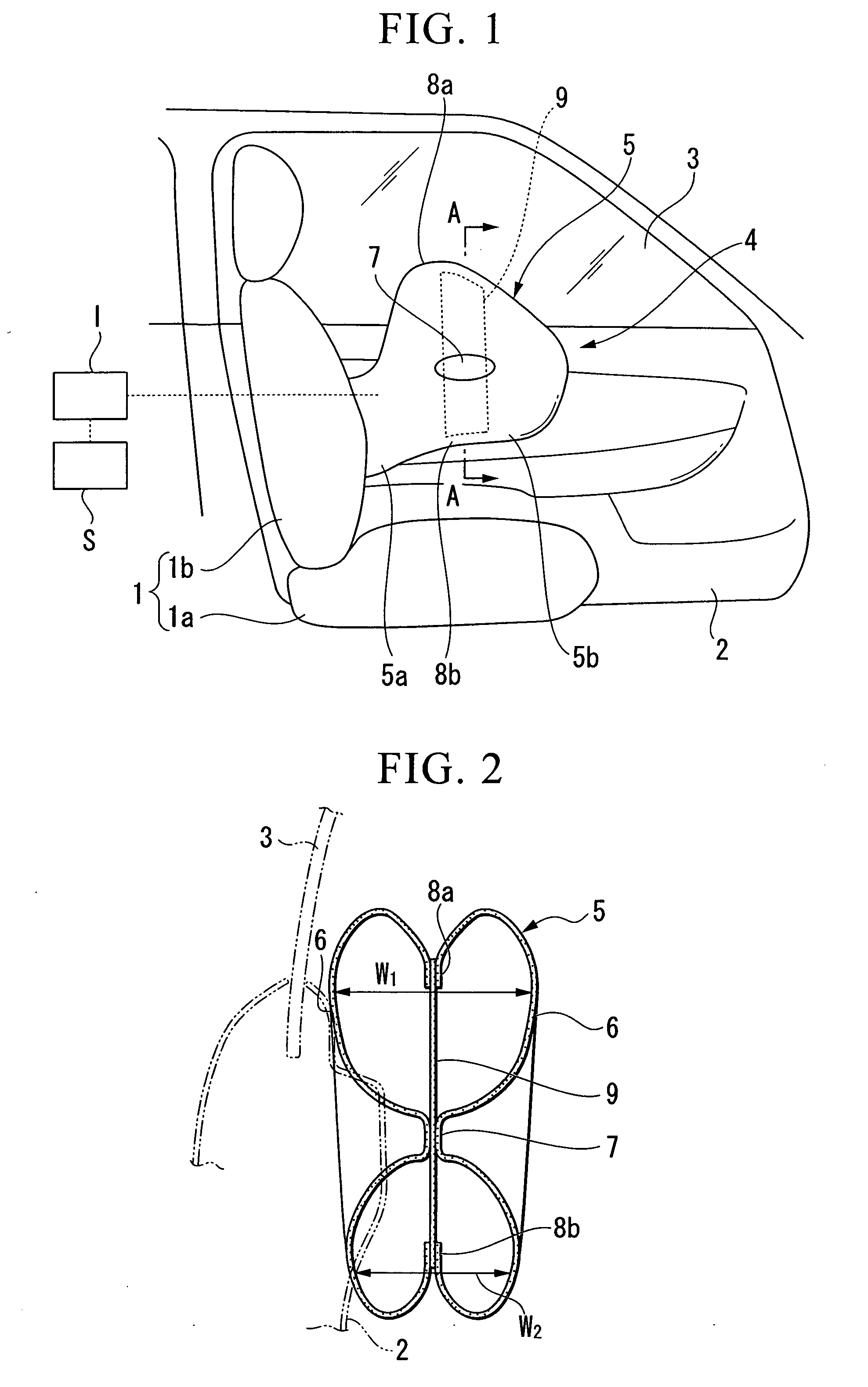
[0028]FIGS. 1 and 2 illustrate a first embodiment of the present invention. Symbol 1 in FIG. 1 denotes a front seat of a vehicle, symbol 1a denotes a seat cushion on which an occupant sits, symbol 1b denotes a seat back that supports the back of the seated occupant, symbol 2 denotes a side door of a vehicle (vehicle body side portion) that is positioned on the side of the seated occupant, and symbol 3 denotes a door glass that is installed in the side door 2. The airbag device 4 (airbag device for a vehicle) according to this invention is housed in the side portion of the seat back 1b. FIG. 1 shows the state in which the airbag device 4 has been actuated.
[0029]The airbag device 4 is provided with a sensor S that detects an impact such as a collision impact, an inflator I that generates high-pressure gas when the sensor detects an impact, and an airbag 5 that deploys by receiving the high-pressure gas from the inflator. The sensor S and the inflator I may be of types that are known i...
second embodiment
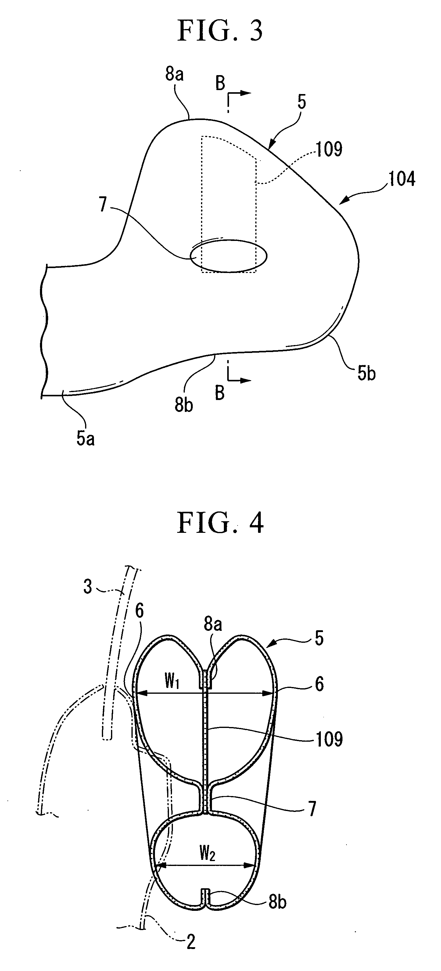
[0037]FIGS. 3 and 4 show a second embodiment of the present invention. In the description hereinbelow including the description of a third embodiment that follows, portions similar to those in the first embodiment shall be given the same symbols and redundant descriptions thereof shall be omitted.
[0038]The basic constitution of an airbag device 104 of the second embodiment is nearly identical to the airbag device 4 of the first embodiment. However, a tether belt 109 thereof is approximately half the length of that of the first embodiment, with the two ends of the tether belt 109 being respectively fixed to the upper joining location 8a and the middle joining portion 7 of the base fabrics 6 that make up the airbag 5. This fixing is performed by the tether belt 109 being interposed between the left and right base fabrics 6 and being simultaneously stitched thereto during the stitching of the left and right base fabrics 6, similarly to the first embodiment.
[0039]The airbag device 104 c...
third embodiment
[0040]FIGS. 5 and 6 show a third embodiment of the present invention.
[0041]The basic constitution of an airbag device 204 of the third embodiment is nearly identical to that of the second embodiment. There are two points of difference, namely, a tether belt 209 is formed to become wider from the lower end to the upper end thereof, and a set length of the tether belt 209 is gathered at the middle portion thereof in the lengthwise direction and stitched (hereinbelow, this portion is referred to as the “gathered portion 15”).
[0042]The airbag device 204 can basically obtain the same effect as the second embodiment. However, since the tether belt 209 is formed to become wider from the lower end to the upper end thereof, it is possible to restrain a wider region of the upper joining location 8a of the airbag 5 without increasing beyond necessity the middle joining portion 7 at which the lower end of the tether belt 209 is fixed. Therefore, even in the case of providing the gathered portio...
PUM
 Abstract
Description
Claims
Application Information