Method for achieving synchronous control of two shafts

A technology of synchronous control and synchronous algorithm, applied in the direction of digital control, electrical program control, etc., can solve the problems of increased cost, resource waste, expensive price, etc., and achieve the effect of fast response speed, large output pulse gap, and poor positioning accuracy

Active Publication Date: 2014-12-24
SHANGHAI ELECTRICAL APP RES INST +1
View PDF1 Cites 19 Cited by
  • Summary
  • Abstract
  • Description
  • Claims
  • Application Information

AI Technical Summary

Problems solved by technology

This greatly increases the cost of the entire system and causes a great waste of resources
Such as the invention patent: a control system of a fixed-length flying saw machine controlled by servo speed-adjusting PLC (201010567491.X), in order to complete the function of synchronizing the slave shaft with the main shaft, Siemens' medium-sized PLC host CPU315-2DP and a high-speed counting expansion module are used FM350-2 and servo driver with profibus communication function, the price of this system is very expensive

Method used


Image

  • Method for achieving synchronous control of two shafts
  • Method for achieving synchronous control of two shafts
  • Method for achieving synchronous control of two shafts

Examples


Embodiment Construction

[0027] In order to make the present invention more comprehensible, preferred embodiments are described in detail below with accompanying drawings.

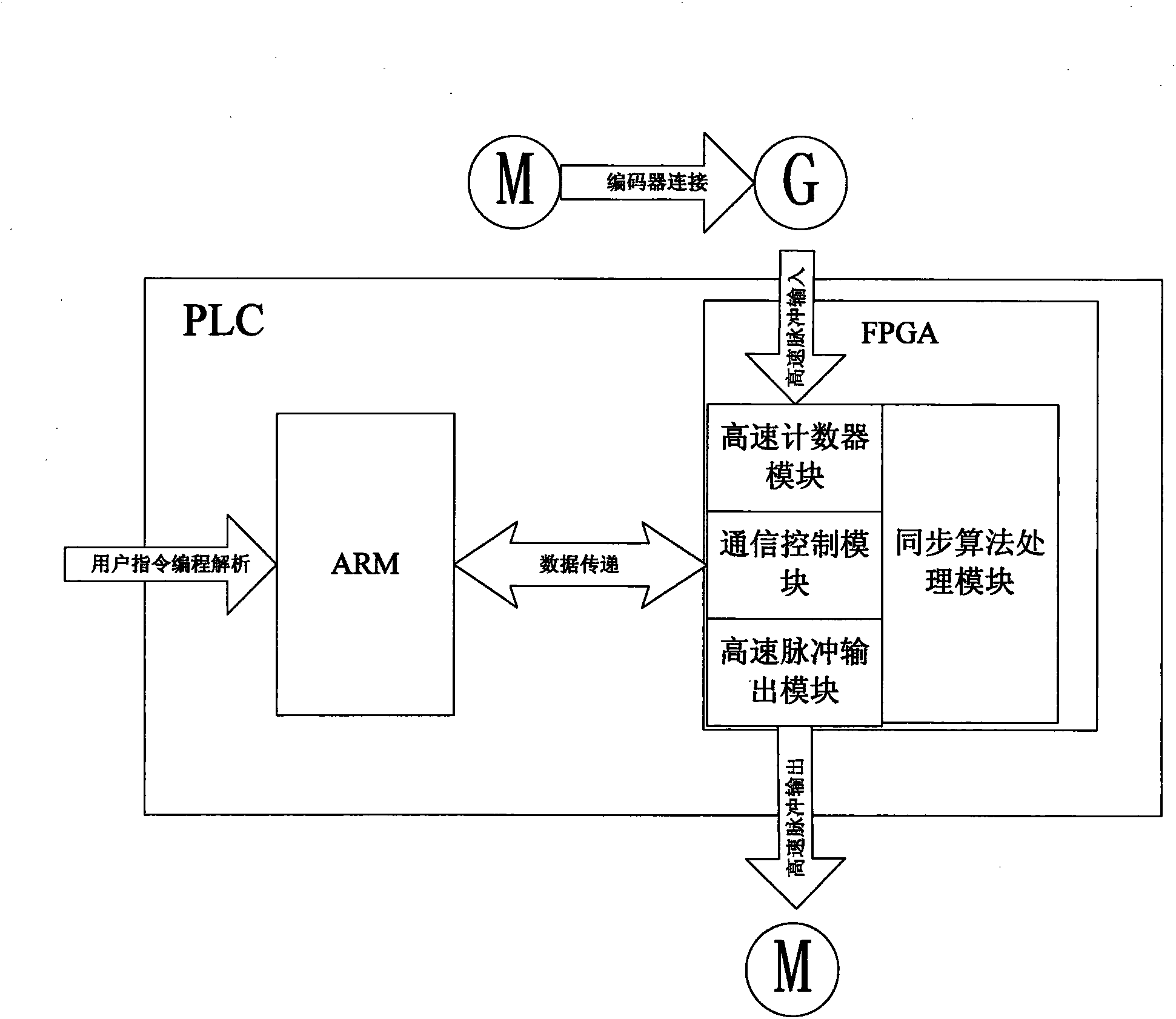
[0028]The method for realizing the synchronous control of two shafts provided by the present invention can complete the synchronous function of master and slave shafts only by using one command. The PLC host in the present invention adopts a main control unit and a synchronous control unit. In this embodiment, the main control unit is realized by an ARM chip, and the synchronous control unit is realized by a large-capacity programmable logic device FPGA. FPGA is responsible for high-speed pulse input sampling, synchronous algorithm processing and high-speed pulse output and other functions. The realization of the synchronization function is completed in the FPGA, and the separation design from the main chip ARM greatly reduces the workload of the main chip and reduces the scanning cycle of the entire PLC.

[0029] Such as figure...


PUM


Abstract

The invention relates to a method for achieving synchronous control of a main shaft and an auxiliary shaft by means of a PLC. The method aims to achieve synchronous control of the two shafts on the premise of low cost. According to the technical scheme, a complex function needing to be achieved through multiple steps in a high-functioning medium or large PLC of other companies just needs to be realized through one instruction in the small PLC used in the method. If the complex function is achieved by using multiple instructions, the sampling period depends on the scanning period of the PLC in most cases; when a PLC program is large, the scanning period is very long, consequently a response lag of the auxiliary shaft is caused, the output pulse interval is large, a motor runs unstably, and positional accuracy is poor. The synchronization instruction is convenient to use and good in synchronization performance. Meanwhile, the execution efficiency of the PLC is greatly improved, and the scanning period of the whole PLC is shortened. Thus, the industrial movement control response is rapider, and position control is more accurate.

Description

technical field [0001] The invention relates to a method for realizing synchronous control of a main shaft and a slave shaft by using PLC. Background technique [0002] PLC (programmable logic controller) is widely used in practical projects because of its high reliability, good real-time performance, powerful functions and convenient use in harsh environments. High-speed pulse output function and high-speed counter function are important components of PLC in the field of position control and motion control. The motor is driven by high-speed pulse output, the speed and direction of rotation of the motor can be sampled by the pulse encoder, converted into pulse form, and then the high-frequency pulse is accurately counted by the high-speed counter, so as to realize the control of the motor by PLC. PLC with these two functions can be applied in various industrial fields such as position control and motion control such as textile machinery and small packaging machinery. [00...

Claims


Application Information

Patent Timeline
Patent Type & Authority Applications(China)
IPC IPC(8): G05B19/18
Inventor 琚长江应成薛吉侯金华程睿远
Owner SHANGHAI ELECTRICAL APP RES INST
Why Eureka
Try Eureka