Method for improving edge touch accuracy of infrared touch screen

An infrared touch screen and edge touch technology, applied in the input/output process of data processing, instruments, electrical digital data processing, etc., can solve the problems of low touch accuracy and low density of optical network arrays, and achieve enhanced scanning accuracy and improved Touch precision, effect of increasing density

Inactive Publication Date: 2015-01-14
BEIJING UNITOP NEW TECH CO LTD
View PDF3 Cites 5 Cited by
  • Summary
  • Abstract
  • Description
  • Claims
  • Application Information

AI Technical Summary

Problems solved by technology

[0008] The technical problem to be solved by the present invention is that the density of the optical network array at the edge of the infrared touch screen in the prior art is low, and the touch accuracy is not high so as to provide a method for improving the touch accuracy of the edge of the infrared touch screen

Method used


Image

  • Method for improving edge touch accuracy of infrared touch screen
  • Method for improving edge touch accuracy of infrared touch screen
  • Method for improving edge touch accuracy of infrared touch screen

Examples


Embodiment 1

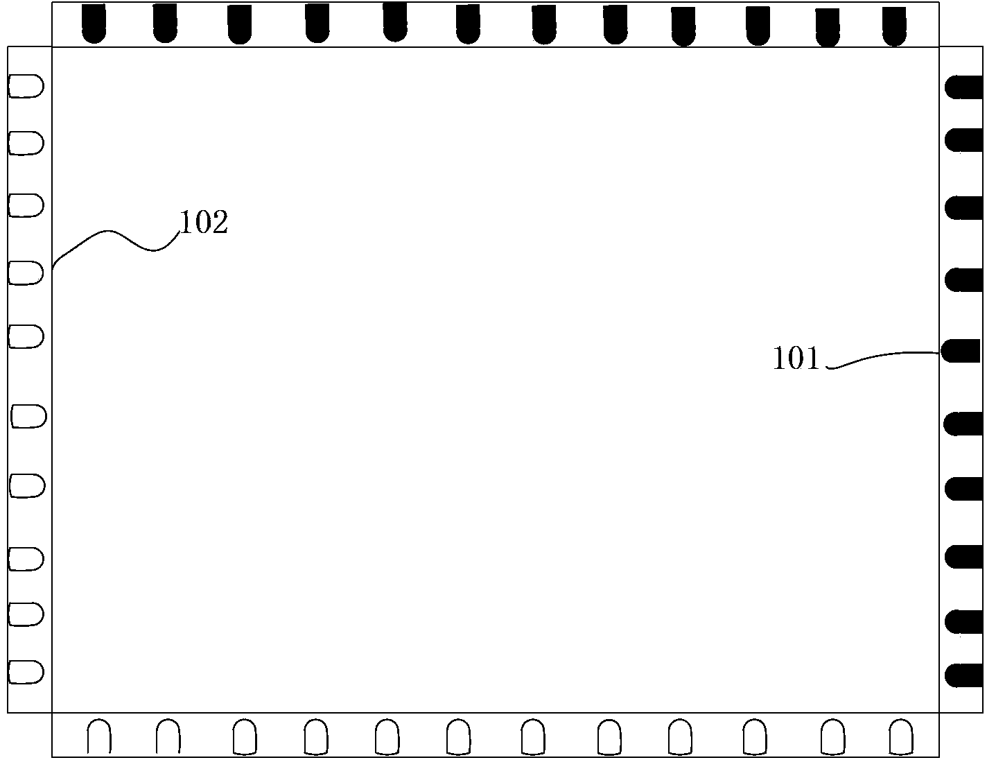
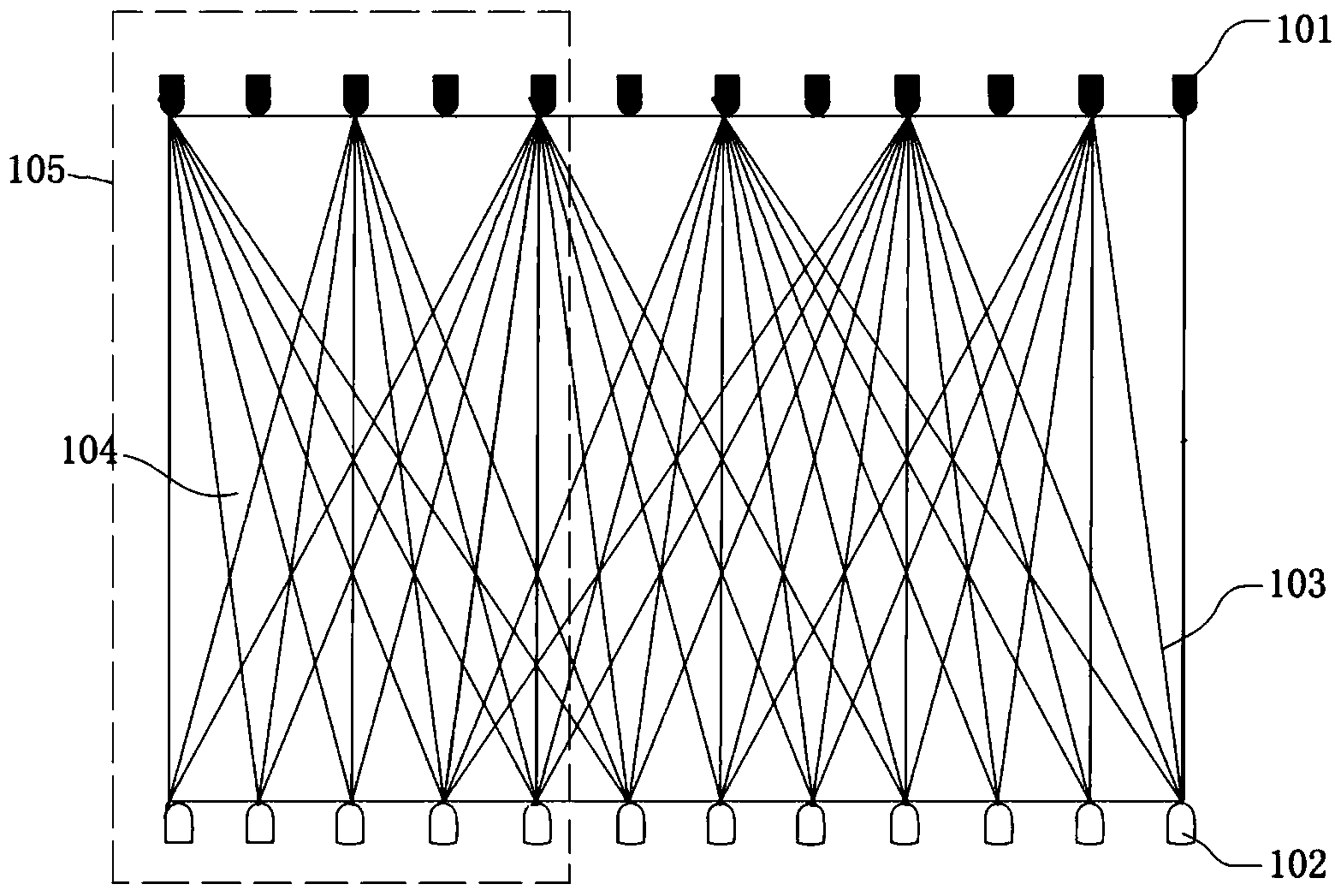
[0031] As an embodiment of the present invention, such as figure 2 As shown, the method for improving the edge touch accuracy of the infrared touch screen is to reduce the edge area of ​​the infrared touch screen by increasing the density of the scanning light 103 in at least one edge area 105 of the infrared touch screen, so that the density of the scanning light 103 in the area near the frame of the infrared touch screen is increased. The area of ​​the optical grid 104 in 105 reduces the size of the largest optical grid 104, improves the resolution of the edge area 105, improves the touch accuracy of the edge area 105, and achieves the purpose of enhancing the touch accuracy of the infrared touch screen. As shown in the figure, the edge area 105 is the area from the frame of the infrared touch screen to the nth infrared emitting tube 101 / infrared receiving tube 102, wherein n is a natural number and ( is the sign of rounding up), and N is the number of infrared receiving...

Embodiment 2

[0040] In this embodiment, a method different from that in Embodiment 1 is adopted to increase the density of the scanning light 103 in the edge region 105 .

[0041] As a specific implementation of this embodiment, the infrared emitting tube 101 and the infrared receiving tube 102 of each edge area 105 adopt a sequential scanning method.

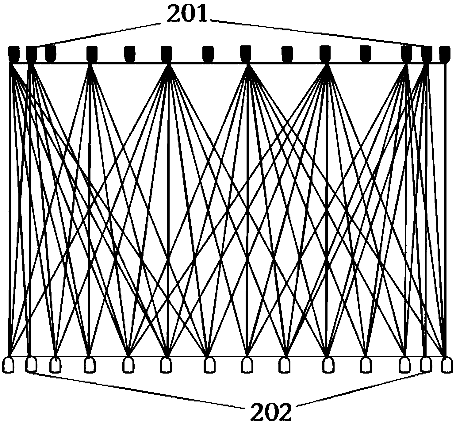
[0042] As another specific implementation of this embodiment, the density of the infrared emitting tube 101 and the infrared receiving tube 102 in the edge area 105 can be increased and the scanning mode of the infrared emitting tube 101 and the infrared receiving tube 102 in the edge area 105 can be changed simultaneously. achieve, such as Figure 6 As shown, the infrared emitting tube 101 , the additional infrared emitting tube 201 , the infrared receiving tube 102 and the additional infrared receiving tube 202 of each of the edge regions 105 adopt a sequential scanning method. through with figure 2 Compared with the method without pro...


PUM


Abstract

The invention relates to a method for improving the edge touch accuracy of an infrared touch screen. The area of optical network grids of the edge of the infrared touch screen is decreased by increasing the density of edge scanning light rays of the infrared touch screen, and accordingly the density of the optical network grids of the whole infrared touch screen is increased, and the purpose of improving the scanning accuracy of the infrared touch screen is achieved. According to the method, the layout of infrared transmitting tubes and infrared receiving tubes of the whole infrared touch screen is not needed to be changed, the density of the scanning light rays in a scanning zone of the infrared touch screen can be increased only by increasing the density of edge scanning light rays of the infrared touch screen, the purpose of improving the scanning accuracy of the infrared touch screen can be achieved. The method for improving the edge touch accuracy of the infrared touch screen has the advantages of being low in manufacturing cost and obviously improving the touch accuracy.

Description

technical field [0001] The invention relates to the technical field of infrared touch screens, in particular to a method for improving the edge touch accuracy of an infrared touch screen. Background technique [0002] Infrared touch screens in the prior art, such as figure 1 As shown, an infrared pair tube array is installed on the frame around the infrared touch screen. The infrared pair tube array includes one-to-one corresponding infrared emitting tubes and infrared receiving tubes, and the interval between adjacent infrared emitting tubes is the same as that of adjacent infrared receiving tubes. The intervals between the tubes are equal, because the layout of equal intervals is beneficial to the analysis and processing of signals, and it is easier to produce. When working, only one infrared emitting tube emits scanning light at a certain moment, and correspondingly, the infrared receiving tube can only receive scanning light in one direction at a certain moment. When th...

Claims


Application Information

Patent Timeline
Patent Type & Authority Applications(China)
IPC IPC(8): G06F3/042
CPCG06F3/0421G06F2203/04103
Inventor 郭洪峰刘新斌管健
Owner BEIJING UNITOP NEW TECH CO LTD
Why Eureka
Try Eureka