Method for improving touch precision of infrared touch screen

An infrared touch screen, high-precision technology, applied in the input/output process of data processing, instruments, electrical digital data processing and other directions, can solve the problem of inability to distinguish, achieve improved touch accuracy, flexible scanning methods, and prevent touch points from jumping. Effect

Inactive Publication Date: 2014-06-11
BEIJING UNITOP NEW TECH CO LTD
View PDF5 Cites 9 Cited by
  • Summary
  • Abstract
  • Description
  • Claims
  • Application Information

AI Technical Summary

Problems solved by technology

[0006] The present invention aims to solve the technical problem that in the prior art, when two dynamic touch points in the touch detection area are very close, the boundary information of each touch point cannot be obtained to distinguish the two touch points, thereby providing a Method for improving touch accuracy of infrared touch screen by effectively distinguishing two touch points and obtaining boundary information of each touch point

Method used


Image

  • Method for improving touch precision of infrared touch screen
  • Method for improving touch precision of infrared touch screen
  • Method for improving touch precision of infrared touch screen

Examples


Embodiment 1

[0046] This embodiment provides a method for improving the touch accuracy of an infrared touch screen, including the following steps:

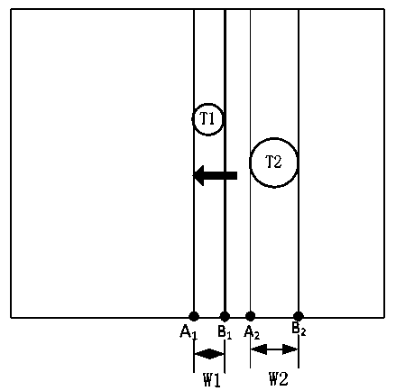
[0047] S1: Scan the touch detection area in the horizontal direction, and when the areas covered by the two touch points are independent of each other, obtain the first touch point T in each frame of data 1 The starting boundary A of the occlusion area 1 , the termination boundary B 1 , width W 1 and the second touch point T 2 The starting boundary A of the occlusion area 2 , the termination boundary B 2 and width W 2 ;Such as image 3 As shown, where the first touch point T 1 The width in the horizontal direction is W 1 =B 1 -A 1 ;Second touch point T 2 The width in the horizontal direction is W 1 =B 2 -A 2 ;

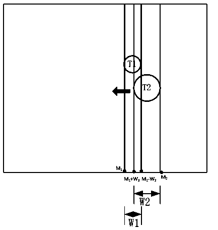
[0048] S2: When the respective occluded areas of the two touch points merge into a whole, obtain the starting boundary of the overall occluded area in the horizontal direction in each frame of data as M 1 , the terminat...

Embodiment 2

[0056] On the basis of embodiment 1, the present embodiment makes the following improvements:

[0057] In the step S1, it also includes the step of obtaining the moving direction of each touch point, and the moving direction of the dynamic touch point is represented by an arrow in the figure, where the moving direction of the touching point refers to the direction of the partial velocity of the touching point in the scanning direction , for vertical scanning, the moving direction of the touch point refers to the direction of the component velocity in the vertical direction;

[0058] In the step S2, the steps of obtaining the horizontal start boundary and end boundary of each touch point in each frame of data are as follows:

[0059] Such as Figure 4 As shown, the real-time acquisition of the overall occlusion area in the lateral direction of the initial boundary is M 1 , the termination boundary M 2 And the overall occlusion area width W, W=M 2 -M 1 ;

[0060] There is ...

Embodiment 3

[0067] In this embodiment, on the basis of Embodiment 2, when two touch point occlusion areas meet and then separate, there may be the following two situations:

[0068] If the relative movement direction of the dynamic touch points in the horizontal direction remains unchanged, after the occlusion areas of the two touch points are separated, the order of the two touch points is exchanged, as in Figure 7 As shown, the original second touch point becomes the current first touch point.

[0069] If the relative movement direction of the dynamic touch point changes in the horizontal direction, the order of the two touch points remains unchanged after the occlusion areas of the two touch points are separated, as shown in Figure 9 shown.

[0070] After the above two touch points are separated, obtain the horizontal start boundary, end boundary and width W of the first touch point occlusion area in each frame of data according to the method of step S1 1 and the horizontal start b...


PUM


Abstract

The invention relates to a method for improving the touch precision of an infrared touch screen. When two touch points have a long distance, the starting boundary, the termination boundary and the width of each touch point in each frame of data can be directly obtained. The width value of each touch point is generally not changed in the moving process, so when the shielding regions of the two touch points are merged into a whole as the distance between the two touch points is near, the boundary information of each touch point can be obtained through calculation according to the starting boundary and the termination boundary of the integral touch shielding region through combining the width of each touch point in a historical frame, so the two touch points with a short distance can be distinguished, the touch point jumping can be prevented, and the touch precision of the infrared touch screen can be improved.

Description

technical field [0001] The invention relates to a method for improving the touch precision of an infrared touch screen, belonging to the technical field of infrared touch screens. Background technique [0002] In the infrared touch screen in the prior art, an infrared pair tube array is installed around the touch detection area. The infrared pair tube array includes an infrared emitting tube and an infrared receiving tube. It is controlled that only one infrared emitting tube emits infrared light at a certain moment, and the corresponding infrared receiving tube receives the infrared light. Therefore, at any moment, if it is detected that a certain infrared receiving tube does not receive infrared light, it can be determined that the infrared light corresponding to the emitting infrared emitting tube and the infrared receiving tube emitting light at this moment is blocked by the touch point. When there is a touch object in the touch detection area, the infrared light betwee...

Claims


Application Information

Patent Timeline
IPC IPC(8): G06F3/042
Inventor 王武军刘新斌
Owner BEIJING UNITOP NEW TECH CO LTD
Why Eureka
Try Eureka