Parts manipulation method and apparatus

a technology of parts and manipulators, applied in the direction of conveyors, conveyors, jigging conveyors, etc., can solve the problems that the function cannot be achieved by any current vibrating device, and achieve the effect of eliminating the uncertainty of the configuration of parts

Active Publication Date: 2007-09-27
NORTHWESTERN UNIV
View PDF14 Cites 11 Cited by
  • Summary
  • Abstract
  • Description
  • Claims
  • Application Information

AI Technical Summary

Problems solved by technology

Some of these functions are not possible by any current vibratory device.

Method used


Image

  • Parts manipulation method and apparatus
  • Parts manipulation method and apparatus
  • Parts manipulation method and apparatus

Examples


embodiments

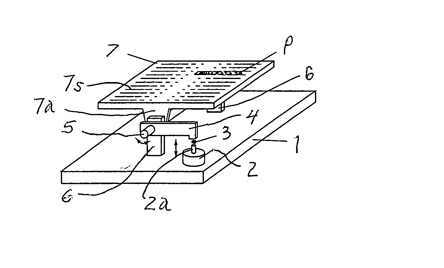
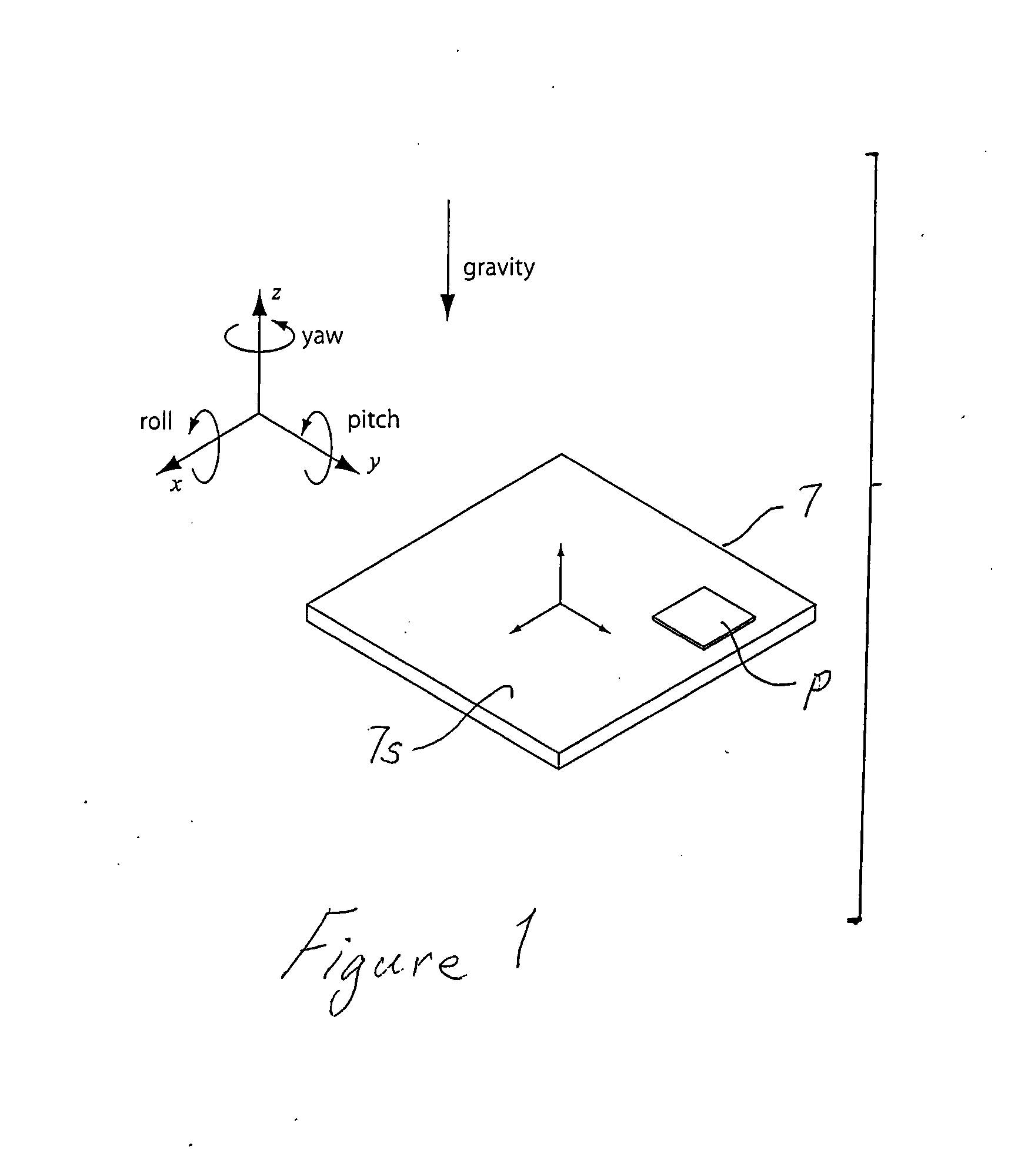
[0051] Apart from the simple motion described above, the invention envisions a broad set of support surface motions to generate a large class of useful force fields. The support surface motion may be any six-degree-of-freedom (x, y, z, roll, pitch, yaw) periodic motion profile, including nonzero roll and pitch, with low amplitude (typically millimeters or microns or less of linear motion, and typically on the order of a degree or less in rotation) and cycle time less than one second. The motion profile may be fixed or it may change under computer control. The support surface may be a flat plate or it may be shaped to modify the force fields generated by vibration. The surface may be largely horizontal or it may be inclined in gravity, to modify the effective force field. For purposes of illustration and not limitation, the case of a flat, largely horizontal support surface is discussed in detail below.

[0052] The set of all periodic six-degree-of-freedom trajectories is an infinite-...


PUM


Abstract

Method and apparatus for imparting movement to one or more articles includes placing the one or more articles on a surface of a support member and imparting vibratory motion to the support member by vibrating actutators connected to the support member wherein the vibratory motion includes at least a rotational vibratory component about one or more axes out-of-alignment with the gravity vector to produce effective force fields on the surface.

Description

[0001] This application claims priority and benefits of provisional application Ser. No. 60 / 782,793 filed Mar. 16, 2006, the entire disclosure of which is incorporated herein by reference.CONTRACTUAL ORIGIN OF THE INVENTION [0002] This invention was supported in part by funding from the Federal Government through the National Science Foundation Grant / Contract IIS-0308224. The Government may have certain rights in the invention.FIELD OF THE INVENTION [0003] The present invention relates to method and apparatus for controlling movement of parts (articles) using force fields established on the parts' support surface by controlled vibration thereof. BACKGROUND OF THE INVENTION [0004] A number of different vibratory devices already exist for industrial applications such as parts feeding. Perhaps the most common industrial vibratory device is the bowl feeder, which uses vibration to advance parts up a helical track in the interior of a bowl while wipers and cutouts reorient or reject inco...

Claims


Application Information

Patent Timeline
Patent Type & Authority Applications(United States)
IPC IPC(8): B65G27/00
CPCB65G27/00B65G27/24B65G27/04
Inventor LYNCH, KEVINUMBANHOWAR, PAUL
Owner NORTHWESTERN UNIV
Why Eureka
Try Eureka