
Back-up ring and sealing assembly

a sealing assembly and back-up technology, applied in the direction of engine seals, mechanical devices, engine components, etc., can solve the problems of reducing subject to extrusion, and the sealing ring cannot always work satisfactorily, so as to reduce the width of the second cut

Inactive Publication Date: 2007-09-27
UTEX IND
View PDF37 Cites 19 Cited by
  • Summary
  • Abstract
  • Description
  • Claims
  • Application Information

AI Technical Summary

Benefits of technology

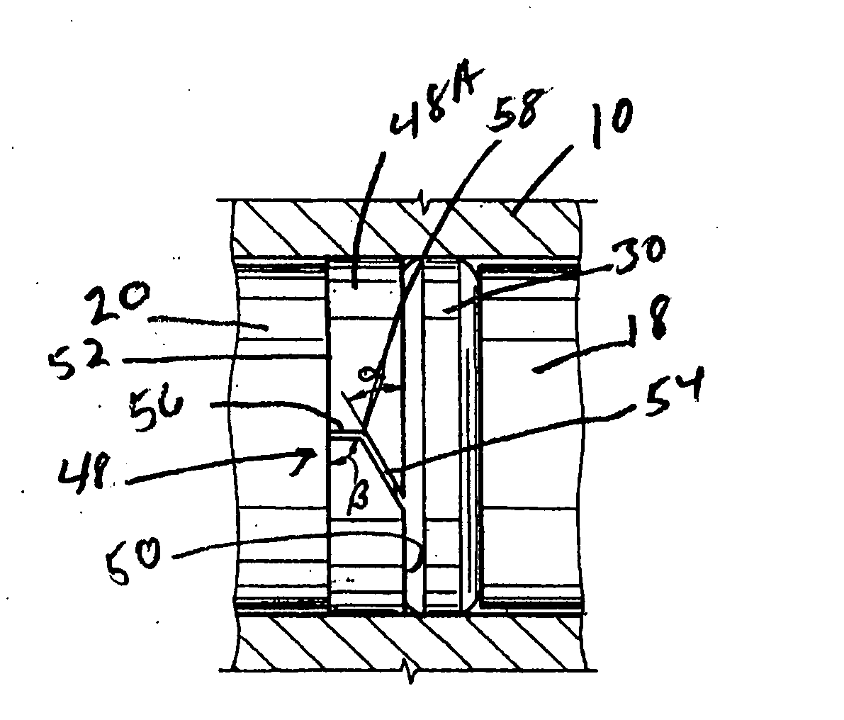
[0010] The present invention, in one aspect, provides a back-up ring for use in a sealing assembly, the back-up ring comprising an annular, split body having a first face, adapted to be engaged by a seal ring and an axially spaced second face. The first and second faces define an axial thickness of the back-up ring. There is a first cut in the first face, the first cut extending to a point intermediate the first and second faces, the first cut...

Problems solved by technology

However, at higher pressures and temperatures the seal rings do not always work satisfactorily.
High temperature may soften the material of the seal ring making it subject to extrusion.
For example, softening of the seal ring under high temperatures can extrude the seal ring into the gap resulting in damage to the seal ring.
In that event the seal ring may be damaged and when the high pressure and high temperature condition is next experienced, the damaged seal ring may not provide an adequate seal.
This problem is exacerbated with each cycle of high pressure and / or high temperature.
However, this can create a poor (non-planar) support surface for the seal ring, and when pressurized can damage the seal and impair its sealing ability.

Method used


Image

  • Back-up ring and sealing assembly
  • Back-up ring and sealing assembly
  • Back-up ring and sealing assembly

Examples


Embodiment Construction

[0032] While the present invention will be described below with respect to sealing between relatively movable members, it is to be understood that it is not so limited and that the sealing assembly and back-up ring of the present invention can be used to seal between any type of radially inner and radially outer members regardless of whether such members are relatively movable, e.g., reciprocable, rotatable, oscillatory, or stationary.

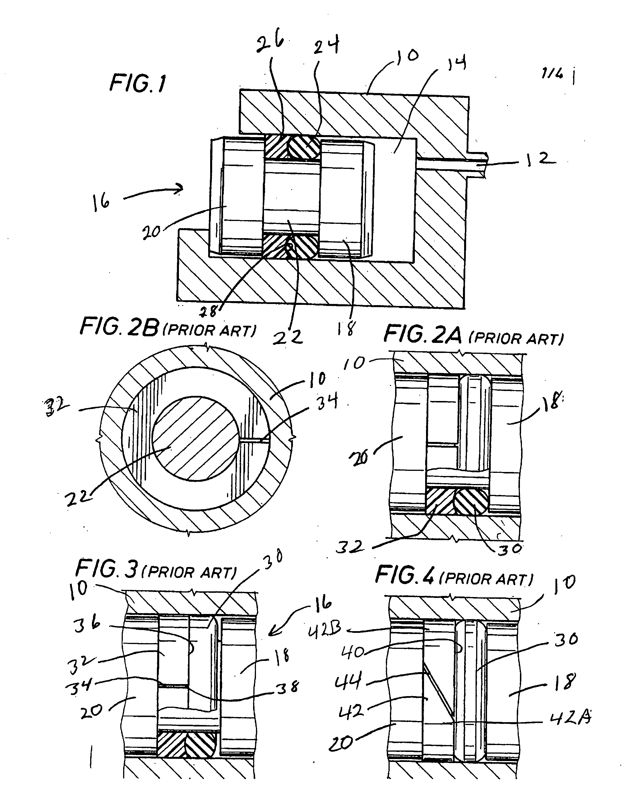
[0033] Turning first to FIG. 1, there is shown a typical arrangement wherein the back-up ring and sealing assembly of the present invention could be employed. Referring then to FIG. 1, there is a pressure housing 10 having a pressure inlet port 12 which communicates with an internal chamber 14 of the housing 10. Disposed in chamber 14 is a piston shown generally as 16 having a first head 18 and a second head 20 connected by piston rod 22. Disposed between heads 18 and 20 and in surrounding relationship to piston rod 22, is an O-ring seal 24 and a spli...


PUM


Abstract

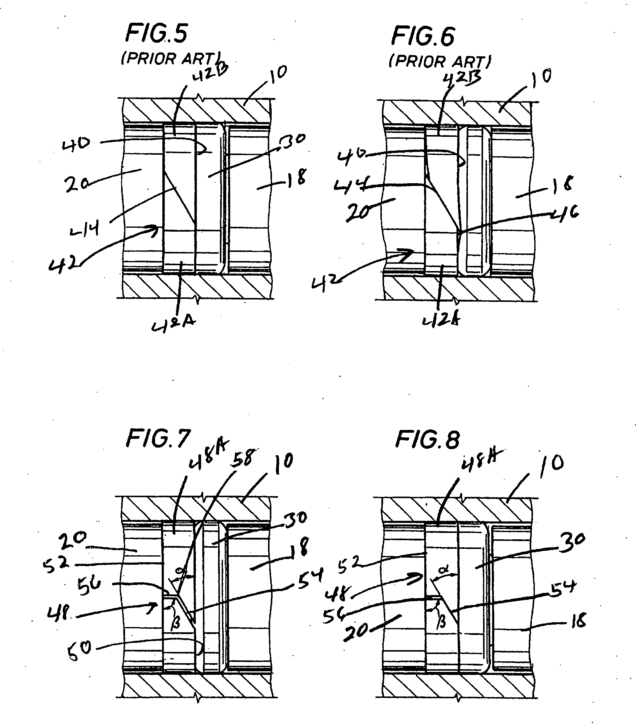
A back-up ring for use in a sealing assembly having an annular body with a first face and a second face and defining an axial thickness, the first face being adapted to be engaged by an annular seal ring, a first cut in the first face extending axially inwardly from the first face at an angle of less than 90° but greater than 0° to the first face, a second cut in the second face, the second cut being interconnected to the first cut and being at an angle thereto, the angle of at least a portion of the second cut being 90° or greater but less than 180° to the second face.

Description

BACKGROUND OF THE INVENTION [0001] 1. Field of the Invention [0002] The present invention relates to sealing assemblies for sealing between radially inner and radially outer members and, more particularly, to a back-up or anti-extrusion ring for use in such assemblies. [0003] 2. Description of Prior Art [0004] Annular seal rings, e.g., O-rings, are frequently utilized to provide a fluid seal between two, radially inner and outer members, e.g., a shaft and a stuffing box, two tubular members, etc. The members can be relatively movable, e.g., rotatable, reciprocating, oscillatory or stationary. [0005] Seal rings generally used are often made of a flexible and / or resilient material, such as natural rubber, synthetic rubber, ethylene-propylene rubbers, PTFE, etc. Seal rings made of these materials provide satisfactory sealing at comparatively low pressures and temperatures. However, at higher pressures and temperatures the seal rings do not always work satisfactorily. High temperature m...

Claims


Application Information

Patent Timeline
IPC IPC(8): F16J15/00
CPCF16J15/166
Inventor STONER, JACK CHAPMAN
Owner UTEX IND
Learn More