

Method and apparatus for balancing energy between portable devices
a technology for balancing energy and portable devices, applied in electric vehicles, transportation and packaging, ac-dc conversion without reversal, etc., can solve the problem that the adapter cannot be used to charge a device it is not designed for
- Summary
- Abstract
- Description
- Claims
- Application Information
AI Technical Summary
Benefits of technology
Problems solved by technology
Method used
Image

Examples
first embodiment
of the Invention
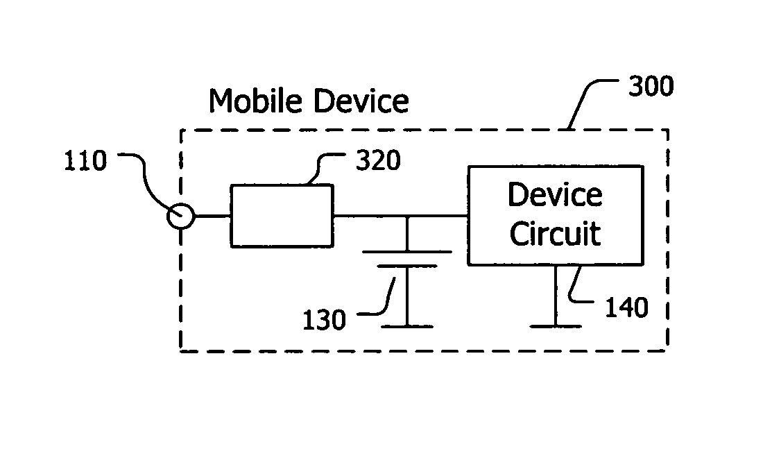
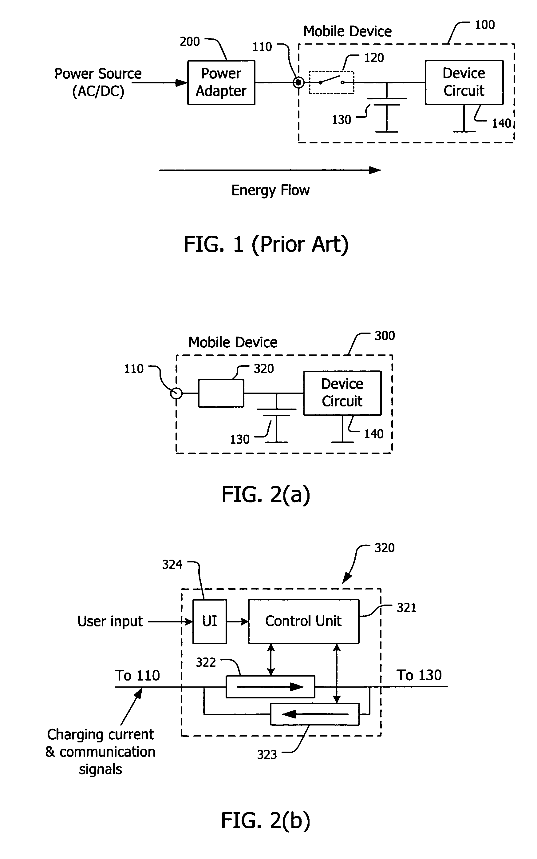
[0045] As shown in FIG. 2(a), a mobile device 300 comprises a power inlet jack 110 for receiving a charging current from an external energy source or for providing a charging current to an external recipient device, one or more circuits 140 (an electrical load) for performing functions of the mobile device, an energy reservoir such as a rechargeable battery 130 for providing electrical energy to the circuits, and a bi-directional charging interface 320 connected between the power inlet jack 110 and the battery 130 / circuit 140.
[0046] As shown in FIG. 2(b), the bi-directional charging interface 320 comprises two energy paths, an inward path 322 and an outward path 323, connected in parallel, a control unit 321 and, optionally, a user interface 324. The control unit 321 is capable of controlling the operation of the inward path 322 and the outward path 323 so as to set a direction for an energy flow between the power inlet jack 110 and the battery 130. The control unit...
example 1
Balancing Energy Between a Device with the Bi-Directional Charging Interface and Another Device Without the Interface
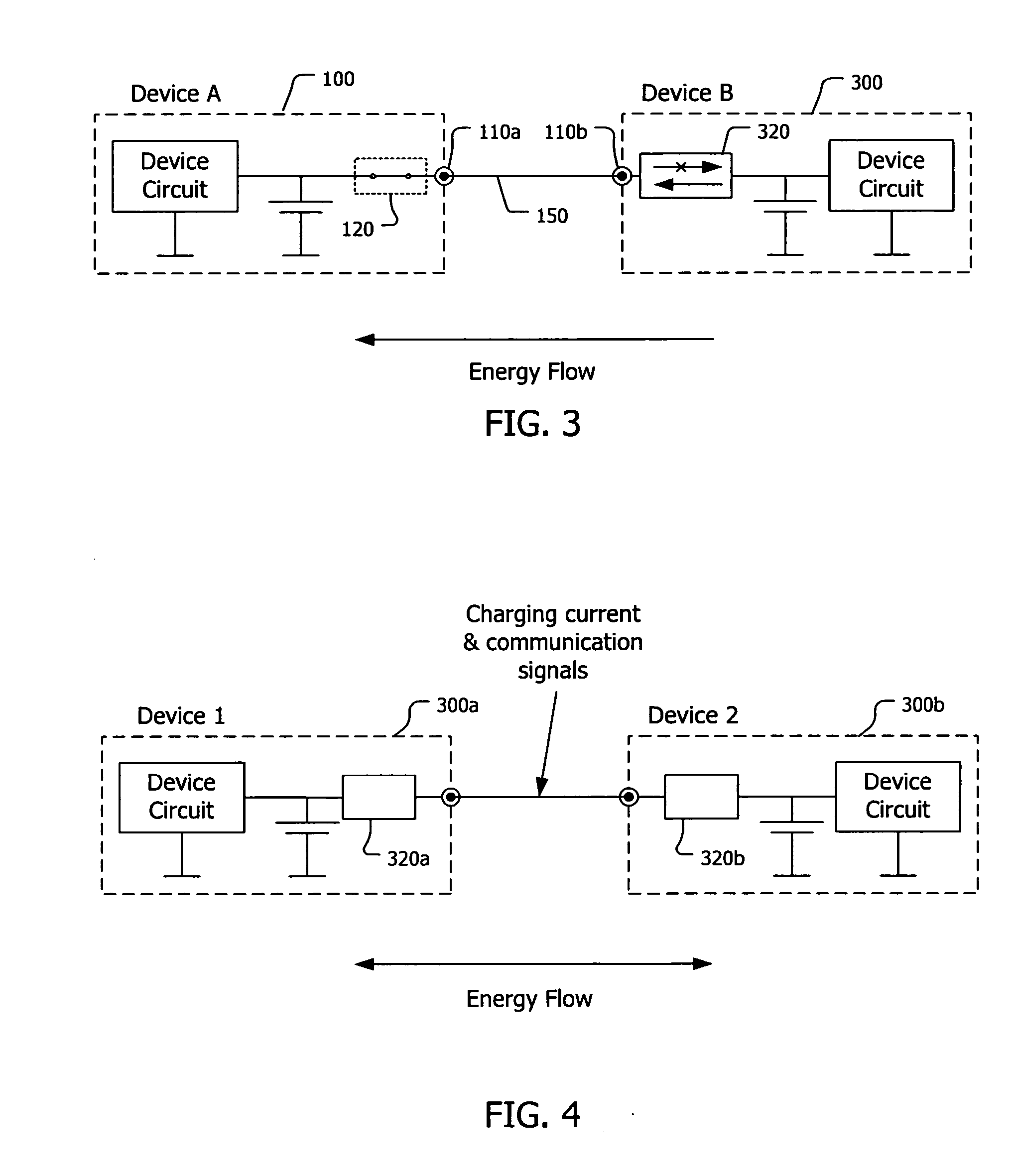
[0049] As shown in FIG. 3, a mobile device 300 (device B) having a bi-directional charging interface 320 is connected to another mobile device 100 (device A). The device A does not have a bi-directional charging interface and the capability to communicate with another device regarding its battery characteristics. The device A only has a one-directional charging interface (such as a switch unit 120) that only allows a charging current flowing into the battery of the device. The device A and the device B are connected to each other by a charging cable 150 at their respective power inlet jacks 110a and 110b. The energy level (represented by a measurable parameter such as battery voltage) of the device A is detected by the device B through the bi-directional charging interface of the device B. Assuming that the battery voltage of the device A is lower than that of the de...
example 2
Balancing Energy Between Two Devices Each Having the Bi-Directional Charging Interface
[0052] As shown in FIG. 4, a first device 300a (device 1) and a second device 300b (device 2), both having the bi-directional charging interface of this invention (320a and 320b), are connected to each other for balancing energy between the devices. The direction of the energy flow can be either from device 1 to device 2, or from device 2 to device 1, depending on the results from a device-to-device communication between the two interfaces. The devices 1 and 2 are connected to each other by a charging cable 150 at their respective power inlet jacks. The charging cable 150 carries the communication signals, as well as the charging current, between the two devices.
[0053] The steps for determining the direction of the current flow are illustrated in FIGS. 5(a) and 5(b). As shown in FIG. 5(a), in the beginning, one end of the charging cable 150 is plugged into the power inlet jack 110a of the device ...
PUM
 Abstract
Description
Claims
Application Information