Versatile system for adaptive mobile station antenna

a mobile station antenna and adaptive technology, applied in the direction of antenna earthings, substation equipment, transmission, etc., can solve the problems of reducing the performance level of the antenna, limiting the amount of power with which an antenna system may transmit, and erode the reliability of communications, so as to minimize or eliminate the impact of variations on device performance and reliability

Inactive Publication Date: 2007-10-11
SAMSUNG ELECTRONICS CO LTD
View PDF7 Cites 84 Cited by
  • Summary
  • Abstract
  • Description
  • Claims
  • Application Information

AI Technical Summary

Benefits of technology

[0008] A versatile system, comprising various apparatus and methods, provides an adaptive antenna system in a mobile communications device. The present antenna system detects certain variations in an operational environment, and adaptively modifies antenna configuration or geometry to minimize or obviate the impact of those variations on device performance and reliability. The present antenna system may be efficiently and cost-effectively implemented in a wide variety of mobile communication devices.

Problems solved by technology

Practically, however, there are several other design concerns that must be balanced against maximizing antenna power.
For example, governmental regulations on SAR (specific absorption ratio) values can limit the amount of power with which an antenna system may transmit.
Physical barriers or obstructions, and sources of signal interference, can degrade antenna performance levels, and erode communications reliability.
To a certain extent, some such deleterious conditions cannot be avoided or obviated.
The proximity of a user's head, hand, fingers or other body component can significantly decrease antenna performance levels.
Close proximity of a body component to an antenna can also increase VSWR (voltage standing wave ratio) levels—decreasing antenna efficiency.
Unfortunately, however, such approaches can add significant expense and commonly provide only suboptimal performance.

Method used


Image

  • Versatile system for adaptive mobile station antenna
  • Versatile system for adaptive mobile station antenna
  • Versatile system for adaptive mobile station antenna

Examples


Embodiment Construction

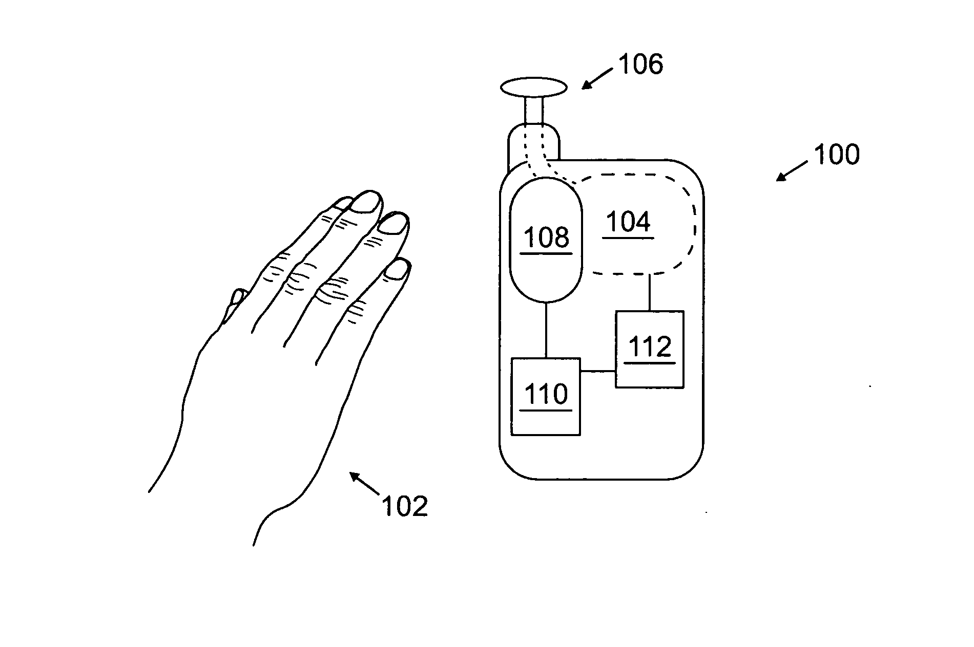
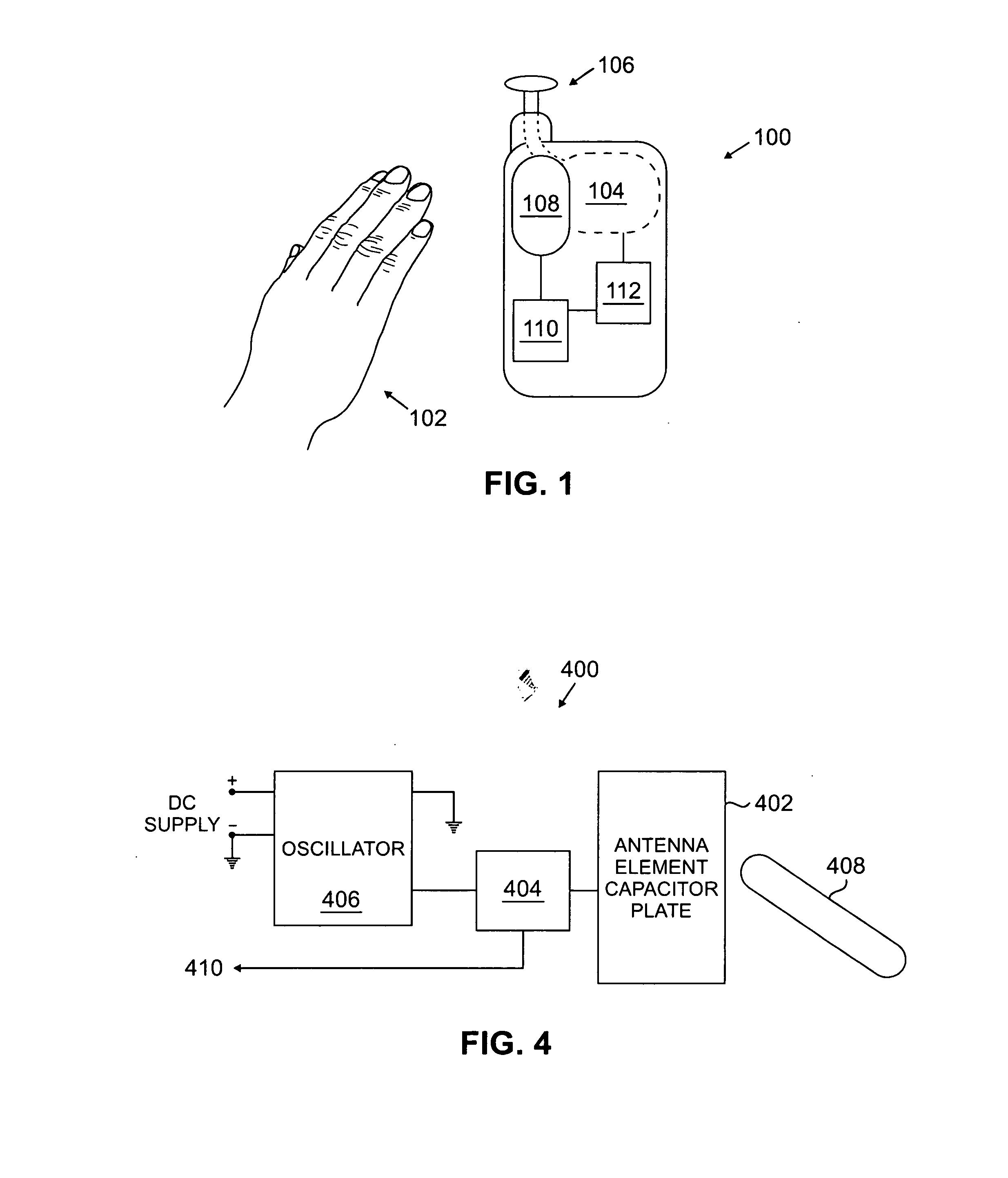
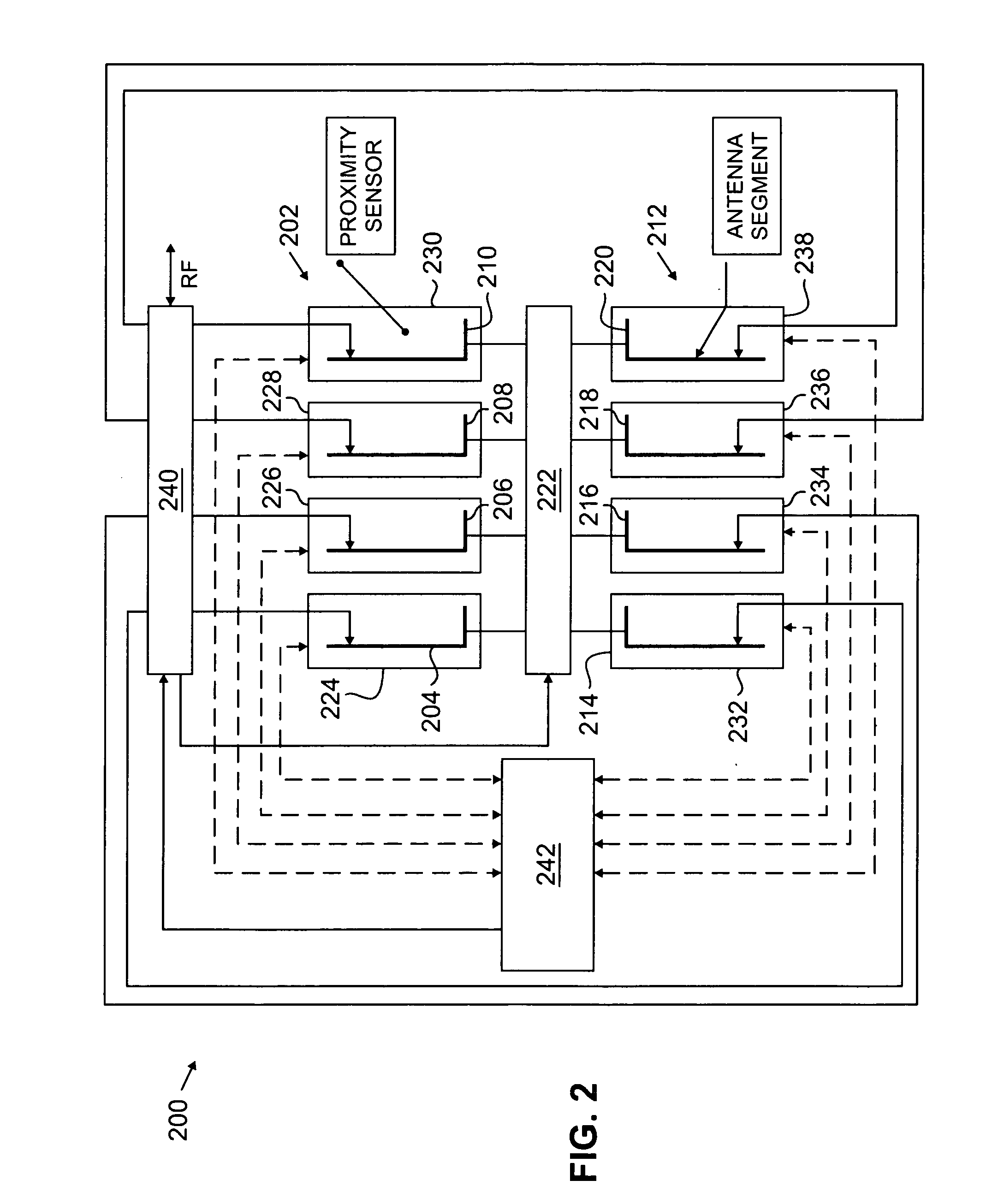
[0016]FIGS. 1-4, discussed below, and the various embodiments used to describe the principles of the present disclosure in this patent document are by way of illustration only, and should not be construed in any way to limit the scope of the disclosure. Hereinafter, certain aspects of the present disclosure are described in relation to illustrative embodiments and operations of mobile communications devices—particularly mobile stations or handsets utilized as mobile phones. Those skilled in the art, however, will understand that the principles and teachings of the present disclosure may be implemented in any suitably arranged mobile communications device or system—regardless of the specific form factor or functionality of that device or system.

[0017] The following discloses a versatile system—comprising various apparatus and methods—for an adaptive antenna in a mobile communications device. The proximity of perturbing objects—sources of interference or obstruction—to an antenna may...


PUM


Abstract

A system for providing an adaptive antenna system in a mobile communications device is disclosed. An array of antenna elements is provided. A sensing component is disposed along a surface of the mobile communications device, proximal to the array of antenna elements. A processor component is communicatively coupled to the sensing component. An implementation element is communicatively coupled to the processor component, and to the array of antenna elements. The sensor component generates data characterizing the proximity of a foreign object to the array of antenna elements; which the processing component uses to determine a configuration for the array of antenna elements. The implementation element modifies the array of antenna elements, responsive to the configuration determined by the processor component.

Description

TECHNICAL FIELD OF THE INVENTION [0001] The present application relates generally to wireless communication devices and, more specifically, to apparatus and methods for providing an adaptive antenna system that overcomes performance losses otherwise due to proximity of an external object to a mobile station antenna. BACKGROUND OF THE INVENTION [0002] Mobile communication devices are fast becoming ubiquitous. These devices commonly utilize one or more antenna systems to facilitate signal transmissions—both transmitting and receiving—with some wireless host system or network. Maximizing the strength and reliability of such transmissions is one common concern in antenna design. Ideally, an antenna of the highest possible power would, in most cases, provide optimal transmission performance. [0003] Practically, however, there are several other design concerns that must be balanced against maximizing antenna power. Most mobile communications devices operate—at least partially—on battery p...

Claims


Application Information

Patent Timeline
Patent Type & Authority Applications(United States)
IPC IPC(8): H04B1/06H04M1/00H04B7/00
CPCH04B1/3838H04B5/0043H04B5/0012
Inventor CHUNG, YONG WOOCLEVELAND, JOSEPH R.
Owner SAMSUNG ELECTRONICS CO LTD
Why Eureka
Try Eureka