Recording and reproducing device

a recording and reproducing device technology, applied in the field of recording and reproducing devices, can solve the problems of difficult transmission of vibration to the whole of the support plate, and achieve the effects of suppressing collision noise, eliminating grating noise, and suppressing collision nois

Inactive Publication Date: 2007-10-11
ORION ELECTRIC CO LTD
View PDF6 Cites 2 Cited by
  • Summary
  • Abstract
  • Description
  • Claims
  • Application Information

AI Technical Summary

Benefits of technology

[0014]According to the third aspect of the invention, vibration transmitted to the support plate from the clamper is absorbed by the resin springs formed on the frame, thus making it difficult for the vibration to be transmitted to the whole of the support plate. Therefore, it is possible to suppress the collision noise between the turntable and the clamper as much as possible.
[0015]A fourth aspect of the invention relates to a recording and reproducing device including a carrying mechanism for carrying a disk-shaped recording medium, a frame for mounting the carrying mechanism, a pickup unit for scanning the recording medium carried in the frame, a turntable for rotating the recording medium, a clamper which is provided at a position opposite to the turntable, and a support plate which is installed between side walls of the frame to secure the clamper, wherein slits are formed at both sides of the support plate, thereby forming mounting pieces having flexibility, and the mounting pieces are secured to the side walls of the frame.
[0016]According to the fourth aspect of the invention, vibration transmitted to the support plate from the clamper is absorbed by the mounting pieces of the support plate, thus making it difficult for the vibration to be transmitted to the whole of the support plate. Therefore, it is possible to suppress the collision noise between the turntable and the clamper as much as possible. Further, since tone quality caused by vibration transmitted to the support plate varies with the length of the slits for forming the mounting pieces, it is possible to eliminate grating noise by adjusting the length of the slits.

Problems solved by technology

Vibration transmitted to the support plate from the clamper is absorbed by the elastic portion, thus making it difficult for the vibration to be transmitted to the whole of the support plate.

Method used


Image

  • Recording and reproducing device
  • Recording and reproducing device
  • Recording and reproducing device

Examples


first embodiment

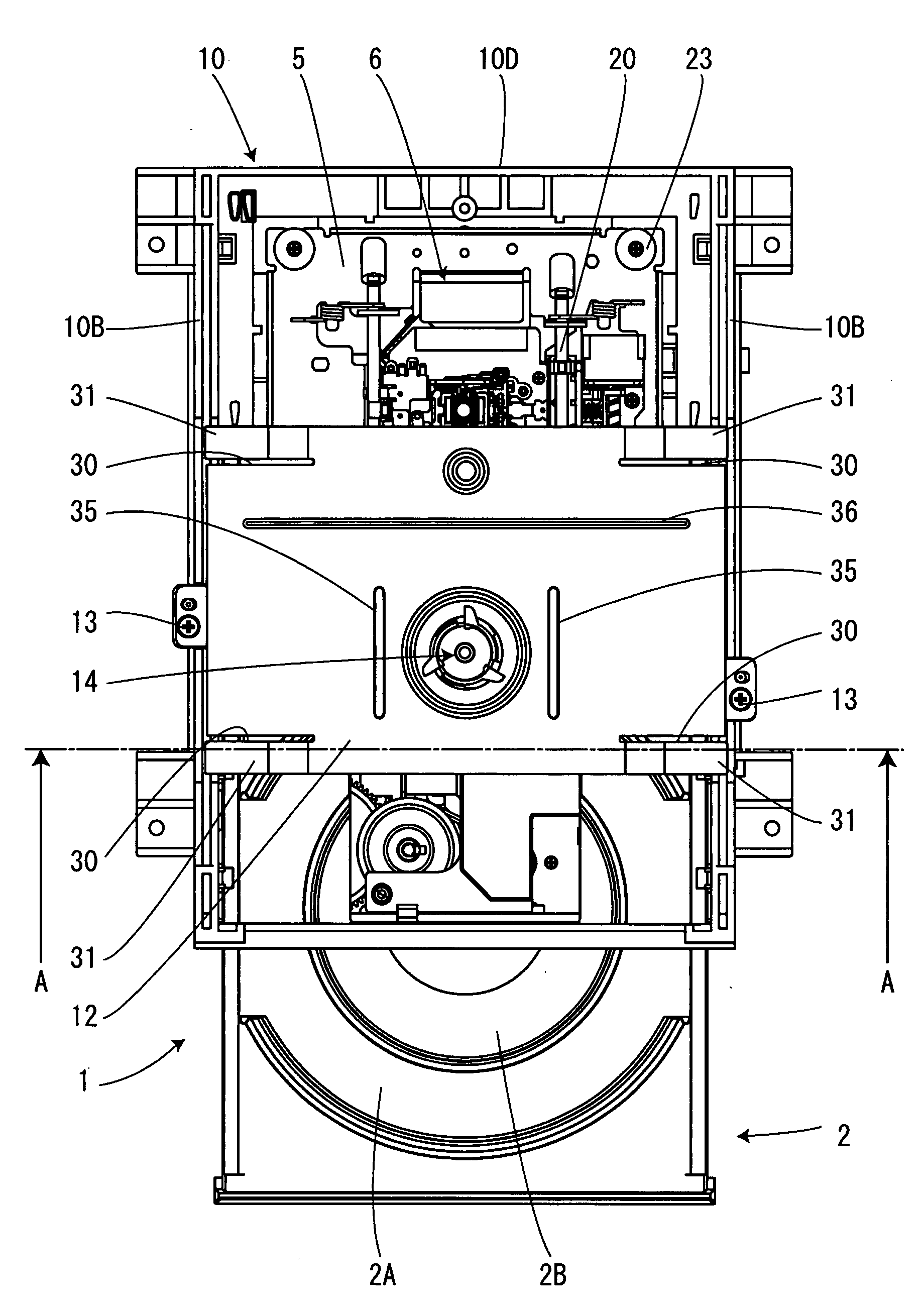
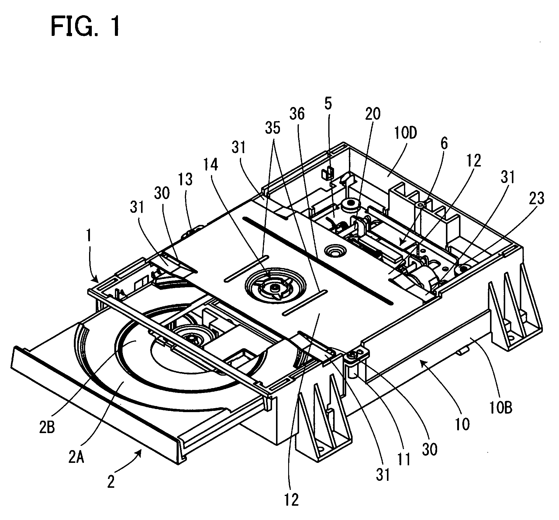
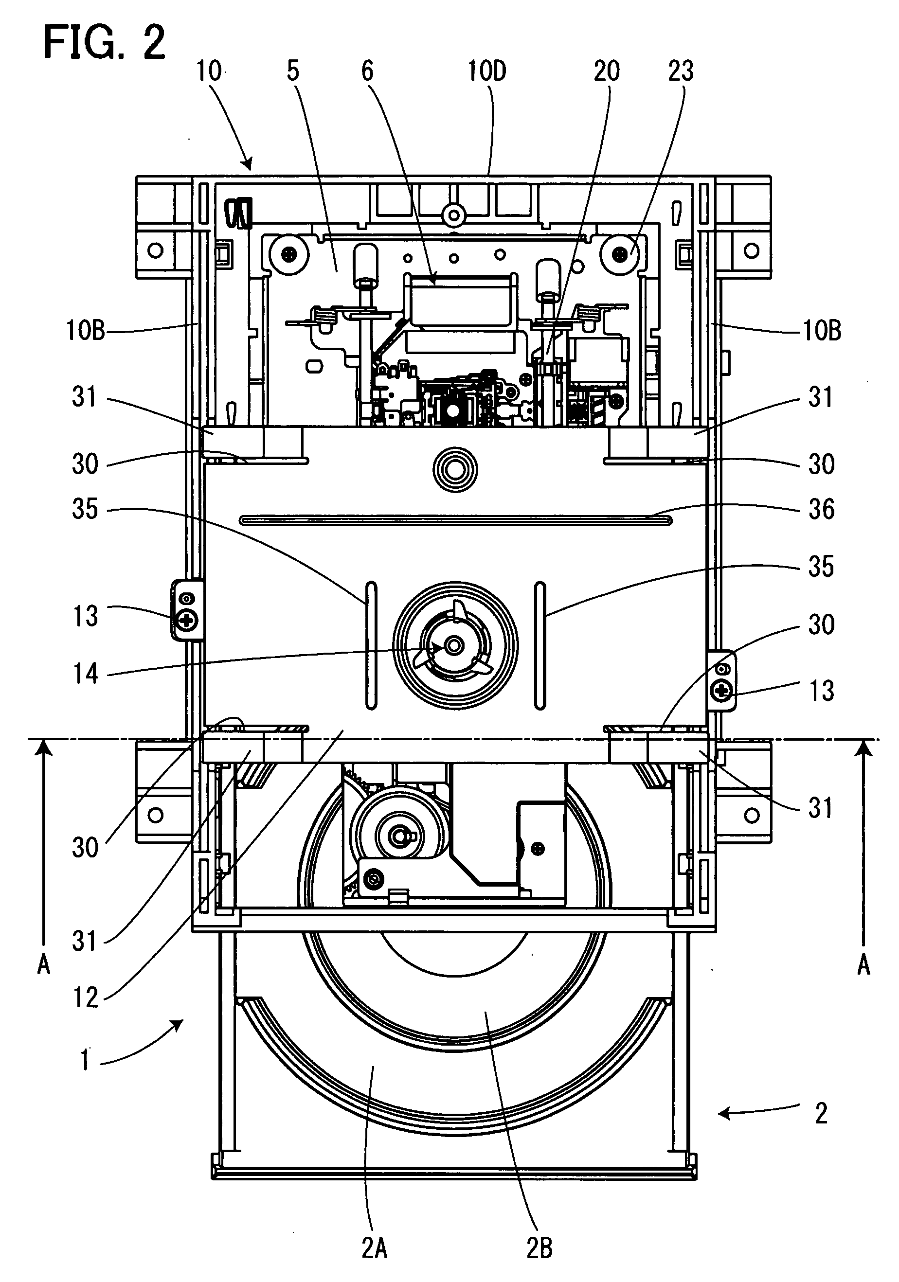
[0031]FIGS. 1 to 5 are illustrations showing a disk device according to a first embodiment of the invention. FIG. 1 is a perspective view of the disk device, FIG. 2 is a plan view of the disk device, FIG. 3 is a cross-sectional view taken along line A-A of FIG. 2, FIG. 4 is a perspective view with a cross section taken along line A-A of FIG. 2, and FIG. 5 is a sectional view of the disk device.

[0032]As shown in FIGS. 1 to 5, in the disk device 1 according to this embodiment, a tray 2 as a carrying mechanism for carrying in and carrying out a disk (not shown), a turntable 3 for rotationally driving the disk, and a pickup unit 4 provided to be movable in and out in the radial direction of the disk are assembled on a metal chassis 5 into a traverse unit 6, and these main components are mounted on a frame 10 made of a synthetic resin.

[0033]The frame 10 is molded of a synthetic resin and formed into a box shape having a bottom. The frame 10 is constructed of a horizontal wall 10A, sidewa...

second embodiment

[0041]FIGS. 6 to 10 are illustrations showing a disk device according to a second embodiment of the invention. FIG. 6 is a perspective view of the disk device, FIG. 7 is a plan view of the disk device, FIG. 8 is a side view of the disk device, FIG. 9 is a cross-sectional view taken along line B-B of FIG. 7, and FIG. 10 is a perspective view with a cross section taken along line B-B of FIG. 7.

[0042]The disk device of this embodiment is substantially the same as that of the first embodiment except the structure of elastic portions. The same portions as those of the first embodiment are denoted by the same reference numerals, and only different portions are described. In the first embodiment, the spring pieces 31 as elastic portions are formed on the support plate 12. However, in this embodiment, resin springs 40 as elastic portions are integrally molded at the side walls 10B of the frame 10 and elastically contacted with the support plate 12. With this structure, when the turntable 3 ...

third embodiment

[0043]FIGS. 11 and 12 are illustrations showing a disk device according to a third embodiment of the invention. FIG. 11 is a perspective view of the disk device, and FIG. 12 is a plan view of the disk device.

[0044]The disk device of this embodiment is substantially the same as those of the foregoing embodiments except the structure of the support plate 12. The same portions as those of the foregoing embodiments are denoted by the same reference numerals, and only different portions are described. In this embodiment, slits 45 are formed at both sides of the support plate 12, thereby forming mounting pieces 46 having flexibility at both sides of the support plate 12. The mounting pieces 46 are secured to the bosses 11 of the frame 10 by the screws 13, with the support plate 12 slightly floated from the frame 10. With this structure, when the turntable 3 collides with the clamper 14, the vibration transmitted to the support plate 12 from the clamper 14 is absorbed by the mounting piece...


PUM

PropertyMeasurementUnit
flexibilityaaaaaaaaaa
attractive forceaaaaaaaaaa
magnetic forceaaaaaaaaaa

Abstract

The present invention reduces contact noise between a turntable and a clamper without increasing the number of components. Spring pieces are formed by forming slit grooves in the corners of a support plate. When the support plate is secured by screws to bosses of a frame, the spring pieces formed in the four corners of the support plate are elastically contacted with the frame, with the support plate slightly floated from the frame. Thereby, vibration transmitted to the support plate from the clamper is absorbed by the spring pieces, thus suppressing noise caused by the vibration transmitted to the support plate.

Description

[0001]The present application is based on and claims priority of Japanese patent application No. 2006-104530 filed on Apr. 5, 2006, the entire contents of which are hereby incorporated by reference.BACKGROUND OF THE INVENTION[0002]1. Field of the Invention[0003]The present invention relates to a recording and reproducing device for rotating a disk-shaped recording medium (hereinafter referred to simply as a disk) grasped by a turntable and a clamper, and more particularly, relates to a recording and reproducing device capable of suppressing contact noise between the clamper and the turntable as much as possible.[0004]2. Description of the Related Art[0005]In general, a recording and reproducing device rotates a recording medium such as a CD (Compact Disk) or a DVD (Digital Versatile Disk), applies laser light from a pickup unit to the recording surface of the recording medium, and receives by the pickup unit the laser light reflected from the recording surface of the recording mediu...

Claims


Application Information

Patent Timeline
Patent Type & Authority Applications(United States)
IPC IPC(8): G11B7/00
CPCG11B17/056G11B17/03
Inventor WATANABE, KAZUHIRO
Owner ORION ELECTRIC CO LTD
Why Eureka
Try Eureka