Torsional vibration damping device

a technology of torsional vibration and damping device, which is applied in the direction of rotating vibration suppression, vibration suppression adjustment, gearing, etc., can solve the problems of damper housing wear, damper deformation, and poor damping performance of the damper housing, so as to prevent the deformation of the cover and allow the rolling mass to oscillate smoothly

Active Publication Date: 2016-11-10
TOYOTA JIDOSHA KK
View PDF5 Cites 9 Cited by
  • Summary
  • Abstract
  • Description
  • Claims
  • Application Information

AI Technical Summary

Benefits of technology

[0012]Thus, according the preferred embodiment, the torsional vibration damping device is provided with the deformation-preventing member to prevent a deformation of the cover that has not been focused on the prior art. Since deformation of the cover is prevented by the deformation-preventing member even if an internal pressure of the torque converter is raised, the rolling mass is allowed to oscillate smoothly. For this reason, vibration damping performance can be improved while limiting frictional damage.
[0013]In the embodiment in which the rib is arranged to serve as the deformation-preventing member, the torsional vibration damping device can be manufactured without requiring additional parts. In addition, in the embodiment in which the rib is formed on the inner face of the cover, the rolling mass can be prevented from being contacted to the cover without elongating an axial length of the torsional vibration damping device.
[0014]In the embodiment in which the brace member is used to serve as the deformation-preventing member, the rolling mass can be prevented from being contacted to the cover without enhancing stiffness of the cover. In the embodiment in which the rib or brace member is provided with the buffer member, collision of the rolling mass against the width end of the bore can be prevented to suppress collision noise.

Problems solved by technology

Consequently, the rolling mass will not be allowed to oscillate freely and hence vibration damping performance becomes poor.
In addition, the rolling mass and the damper housing may be worn and damaged.

Method used


Image

  • Torsional vibration damping device
  • Torsional vibration damping device
  • Torsional vibration damping device

Examples


Embodiment Construction

)

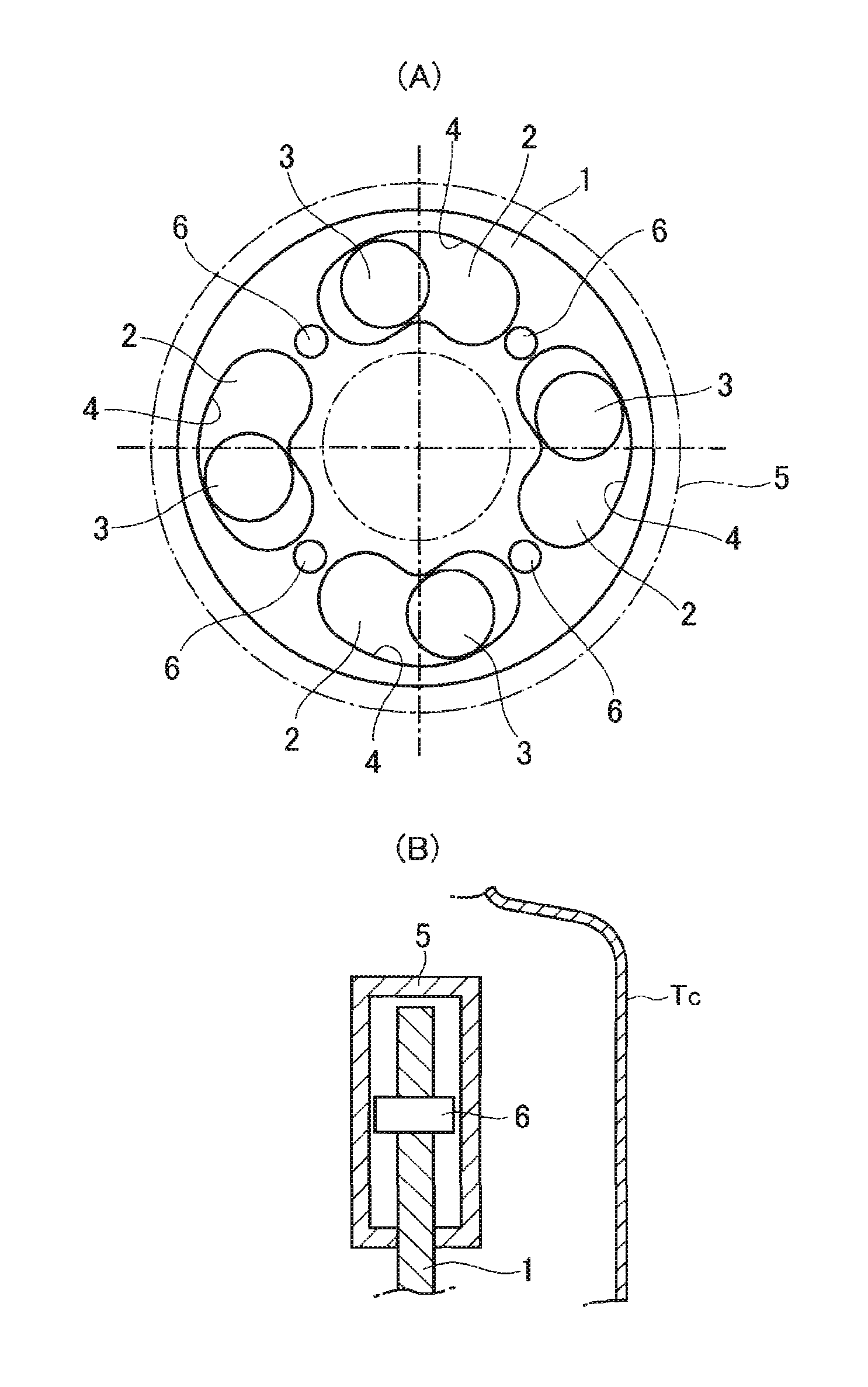
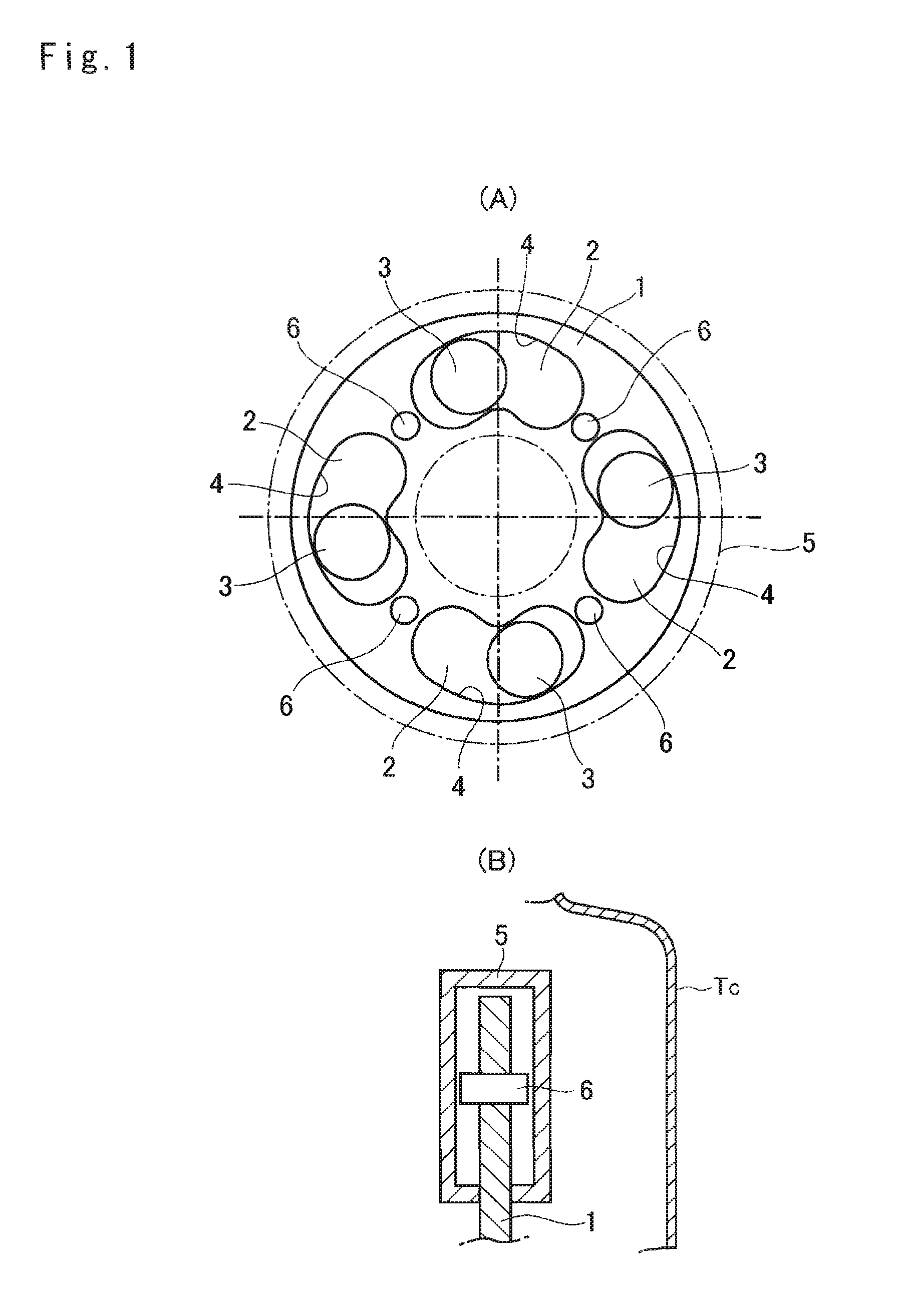
[0020]A preferred embodiment of the present invention is schematically shown in FIG. 1. A rotary member (i.e., a plate) 1 is fitted onto another member to suppress torsional vibrations. A plurality of bores 2, specifically, four bores 2 are formed on an outer circumferential portion of the rotary member 1 in such a manner to penetrate through the rotary member 1 in a thickness direction (i.e., in a direction parallel to a rotational center axis). As depicted in FIG. 1, each bore 2 is individually shaped into a kidney shape whose curvature is larger than that of the outer circumference of the rotary member 1. A rolling mass 3 is individually held in each of the bore 2 in such a manner to be oscillated by an inertial force resulting from torque pulse of the rotary member 1. During rotation of the rotary member 1, each of the rolling mass 3 is pushed onto an inner surface (or an inner edge) as a raceway surface 4 and oscillated along the raceway surface 4. Specifically, a portion of t...


PUM


Abstract

A vibration damping device that can prevent interference between a rolling mass and a cover resulting from deformation of the cover caused by pressure rise, and that can suppress noises is provided. The torsional vibration damping device comprises: a rotary member that is arranged in a torque converter; a rolling mass that is oscillated relatively to the rotary member by torque pulse; a bore that is formed on an outer circumferential portion of the rotary member in such a manner as to penetrates through the rotary member in a direction parallel to a rotational center axis; a cover that covers the rolling mass and the bore liquid-tightly to protect from oil in the torque converter; and a deformation-preventing member that prevents a deformation of the cover in a direction toward the rolling mass.

Description

TECHNICAL FIELD[0001]This invention relates to the art of a device for damping torsional vibrations utilizing reciprocating motion or oscillating motion of an inertial mass.BACKGROUND ART[0002]One example of this kind of device is described in Japanese Patent Laid-Open No. 2012-197886. In this device, a rolling mass is oscillated by torque pulses of a rotary member, and the vibrations of the rotary member are suppressed by an oscillating motion of the rolling mass. The device taught by Patent Laid-Open No. 2012-197886 is used in a torque converter. In order to protect the rolling mass and a raceway surface from oil, the rolling mass is held in a chamber closed liquid-tightly by a damper housing.[0003]In order to ensure the oscillating motion of the rolling mass, the rolling mass is arranged in such a manner as not to be contacted to the damper housing. However, a hydraulic pressure in the torque converter is raised when the torque converter is rotated at a high speed. In addition, t...

Claims


Application Information

Patent Timeline
Patent Type & Authority Applications(United States)
IPC IPC(8): F16F15/14
CPCF16F15/145F16H2045/0263F16H45/02
Inventor MIYAHARA, YUAMANO, HIROYUKI
Owner TOYOTA JIDOSHA KK
Why Eureka
Try Eureka