Degasifier

a degasifier and liquid technology, applied in liquid degasification, separation processes, filtration separation, etc., can solve the problems of corroding the tubes through which a liquid flows, uneven liquid application, and decrease in heat exchanger effectiveness and pressur

Inactive Publication Date: 2007-10-18
NITTO DENKO CORP
View PDF11 Cites 38 Cited by
  • Summary
  • Abstract
  • Description
  • Claims
  • Application Information

AI Technical Summary

Benefits of technology

[0007] According to the present invention, a degasifier is obtained that has a configuration in which using a container in which a first slope having a predetermined angle and orientation is formed in the inner circumference portion in the vicinity of the opening thereof and a cover in which a second slope having a predetermined angle and orientation is formed in a ...

Problems solved by technology

A dissolved gas in a liquid may cause corrosion of tubes through which a liquid flows, decrease in heat exchanger effectiveness and pressure due to bubble generation, or uneven application of a liquid due to generated bubbles.
However, members contained in the housing 102, for example,...

Method used


Image

  • Degasifier
  • Degasifier
  • Degasifier

Examples


examples

[0037] Hereinafter, the present invention is described in more detail using examples. The present invention is not limited to the examples described below.

[0038] In the examples, degasifiers like the degasifier 1 shown in FIG. 1 were produced and the sealing properties thereof were evaluated.

[0039] First, the method of producing each sample that was evaluated in each example is described.

example sample 1

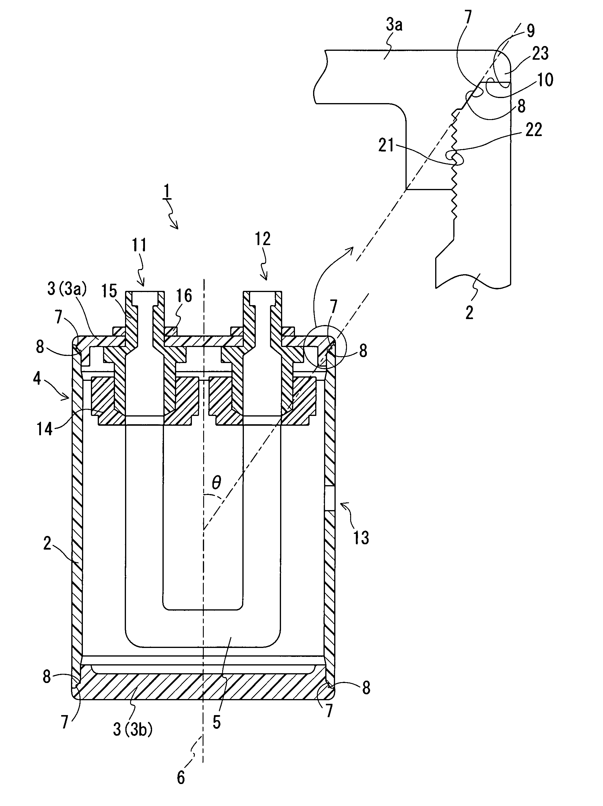
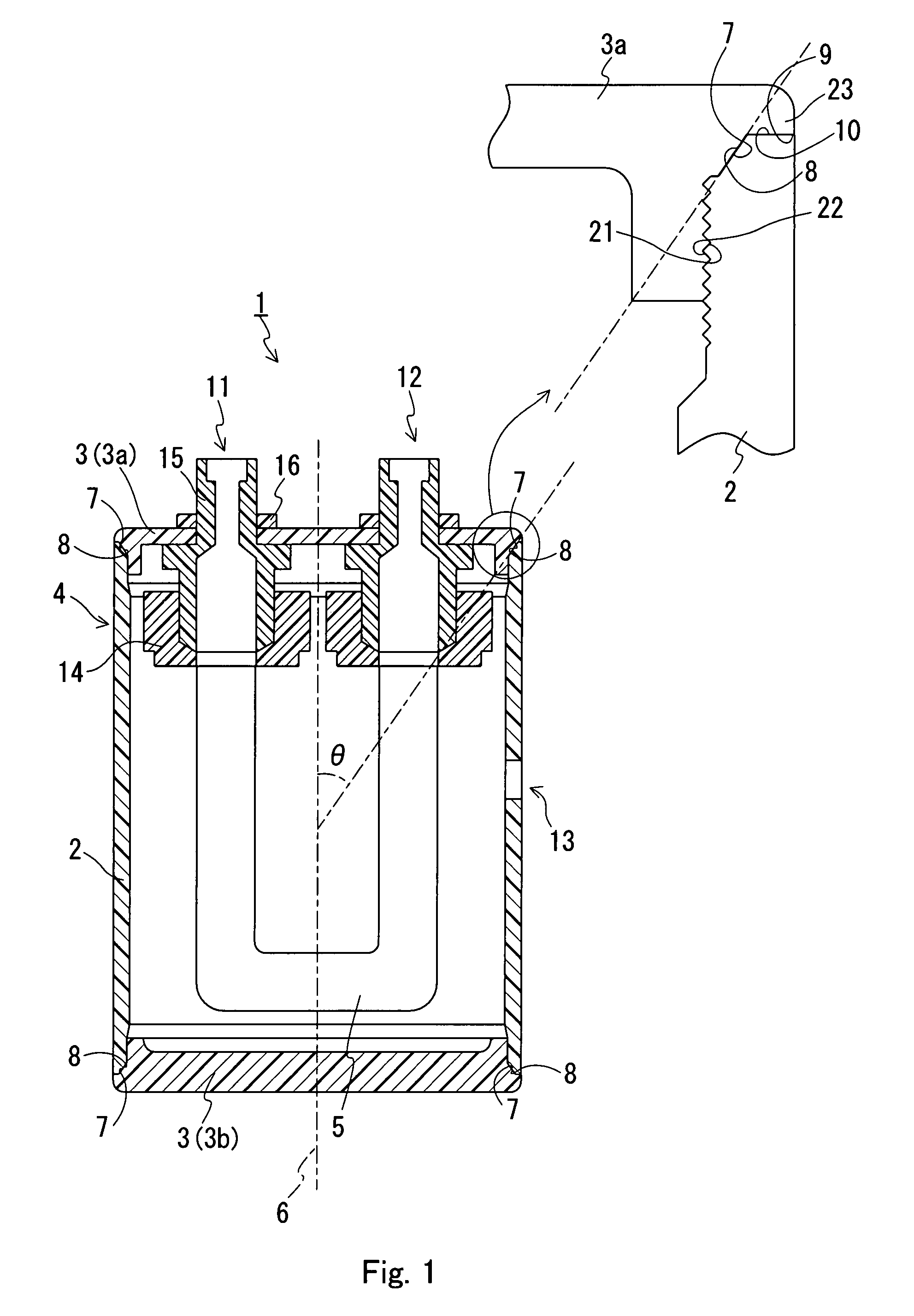
[0040] First, a cylindrical pipe (with an inner diameter of 10 cm) made of polypropylene was cut into a length of 27 cm. Then, as shown in FIG. 1, first slopes 7 and first threaded portions 21 were formed in the inner circumference surfaces in the vicinities of the openings of the pipe. Thus, a container 2 was obtained. In this process, the angle θ to be formed between a first slope 7 and the central axis 6 was set at 60° while the pitch of the first threaded portions 21 was set at 2.0 mm. Furthermore, a connection port 13 for connecting a decompression device to the container 2 was formed in the side face of the container 2.

[0041] Next, through extrusion molding and cutting of polypropylene, a pair of covers 3a and 3b having the shapes shown in FIG. 1 was formed. Each of them had a second slope 8 and a second threaded portion 22 that were formed in its side face. In one 3a of the covers, an inlet 11 and an outlet 12 were formed.

[0042] Next, the container 2 and the cover 3b that w...

example sample 2

[0045] A degasifier 1 was formed in the same manner as in Sample 1, which was used as Sample 2. In this sample, however, the angle θ was set at 85°.


PUM

PropertyMeasurementUnit
Angleaaaaaaaaaa
Angleaaaaaaaaaa
Angleaaaaaaaaaa

Abstract

A degasifier is provided in which the deterioration in sealing property (deterioration in airtightness) is prevented while sealing members to be placed between a container and covers that compose a decompression chamber can be omitted. A degasifier includes a decompression chamber provided with a container and covers, and a gas-permeable tube. The container is a tubular body extending along the central axis. The covers seal the openings of the ends of the tubular body. The gas-permeable tube is contained in the decompression chamber in such a manner that a liquid to be degassed that has entered from the outside of the decompression chamber flows therethrough and the liquid to be degassed that has flowed therethrough flows out of the decompression chamber. The inner circumference surfaces in the vicinities of the openings of the container each are provided with a first slope that is formed to be tilted at a predetermined angle θ with respect to the central axis and to extend away from the central axis toward the opening side of the container. A portion of each of the covers that is in contact with the container is provided with a second slope that is formed to be tilted at the angle θ with respect to the central axis and to extend to approach the central axis toward the inner side of the decompression chamber, with the openings being sealed. The openings are sealed with the container and the covers being joined to each other in the state where the first slopes and the second slopes are in contact with each other, respectively.

Description

TECHNICAL FIELD [0001] The present invention relates to a degasifier that removes gases from a liquid. BACKGROUND ART [0002] A dissolved gas in a liquid may cause corrosion of tubes through which a liquid flows, decrease in heat exchanger effectiveness and pressure due to bubble generation, or uneven application of a liquid due to generated bubbles. Hence, depending on the method and purpose of using a liquid, degassing is required. [0003] For instance, a separation membrane module (see FIG. 2) that is disclosed in JP2002-253936A (Reference 1) can be used for degassing a liquid (a liquid to be degassed). The separation membrane module 101 shown in FIG. 2 is provided with a tubular housing 102 and flanges 103 that seal the openings of the housing 102. In the separation membrane module 101, polytetrafluoroethylene (PTFE) porous tubes 109 are contained in the housing 102 as gas-permeable tubes. The respective ends of the PTFE porous tubes 109 are connected to an inlet (liquid inlet) 10...

Claims


Application Information

Patent Timeline
IPC IPC(8): B01D19/00
CPCB01D19/0031B01D19/00B01D61/00B01D71/36
Inventor OOYA, HAJIME
Owner NITTO DENKO CORP
Why Eureka
Try Eureka