Fuel pump control

a technology of fuel pump and control panel, which is applied in electrical control, pedestrian/occupant safety arrangement, tractors, etc., can solve the problems of increasing difficulty in the calibration and packaging of inertia switches, and achieve the effect of removing the inertia switch of the vehicl

Active Publication Date: 2007-10-18
FORD GLOBAL TECH LLC
View PDF18 Cites 11 Cited by
  • Summary
  • Abstract
  • Description
  • Claims
  • Application Information

AI Technical Summary

Benefits of technology

[0010] The present invention has the advantage of eliminating an inertia switch of a vehicle by utilizing the vehicle's restraint control module to sense a vehicle impact and provide a means via an electronic fuel pump relay to disable the fuel pump. The received signal from the restraint control module is preferably a frequency modulated signal which assists in determining the validity of the received signal before deploying the fuel cut-off. The present invention includes the added benefit of allowing the powertrain control module to variably control the fuel pump in a mechanical returnless fuel system by using pulse width modulation via the electronic fuel pump relay.

Problems solved by technology

A disadvantage with the inertia switch is that proper calibration and packaging of the inertia switch is becoming increasingly difficult due to the characteristics of current vehicle structures.

Method used


Image

  • Fuel pump control
  • Fuel pump control
  • Fuel pump control

Examples


Embodiment Construction

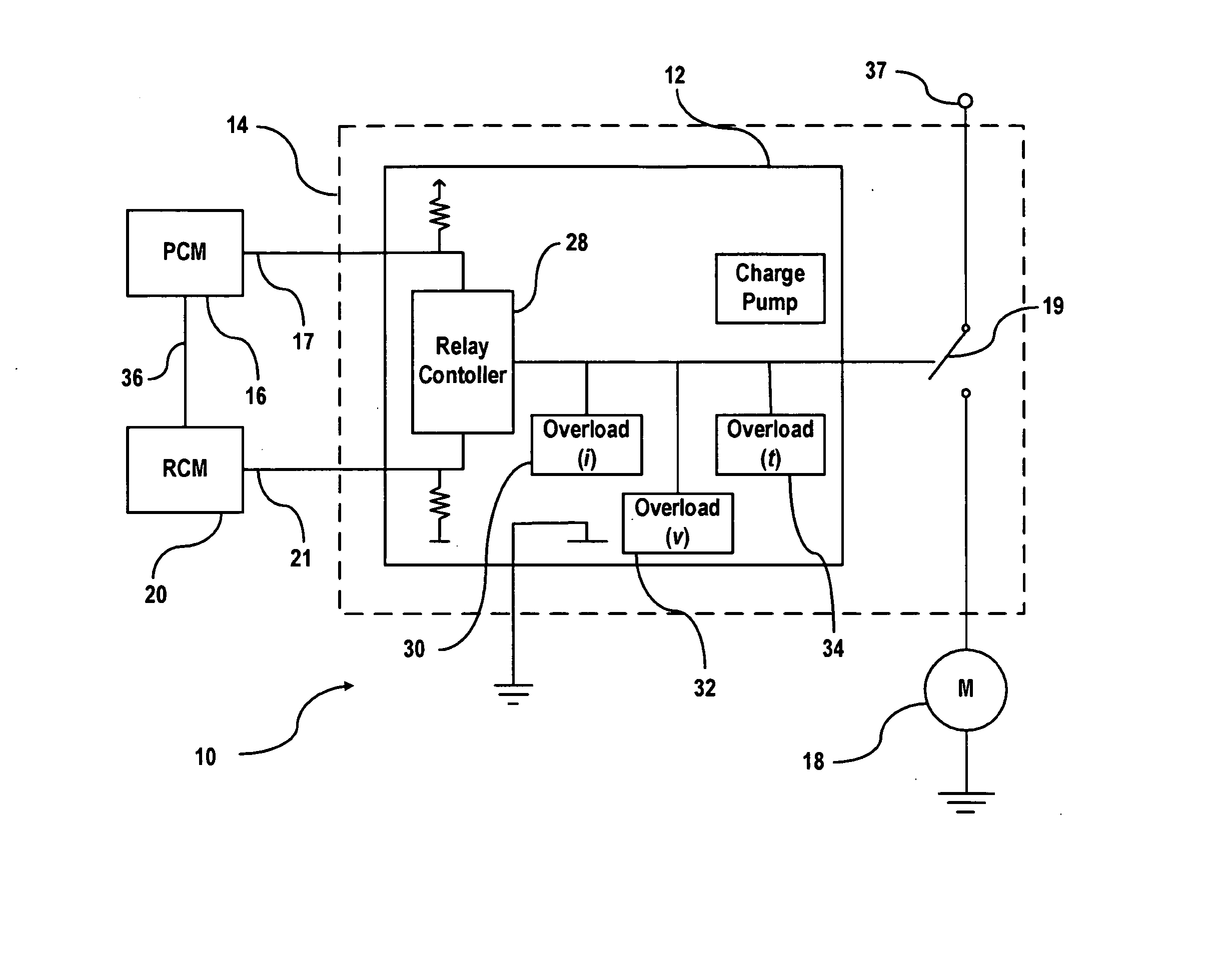
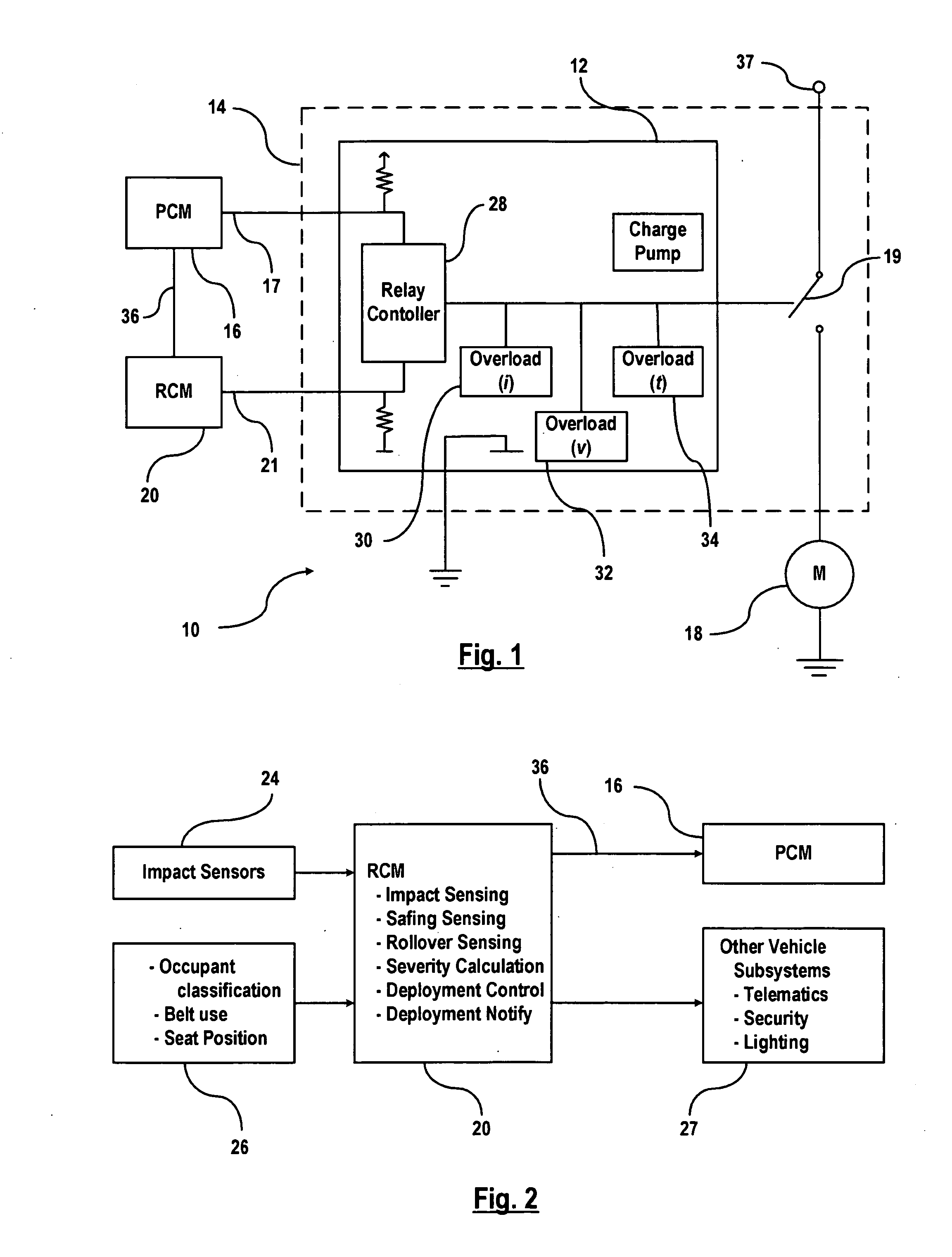
[0020] Referring now to the drawings, there is illustrated in FIG. 1 a fuel pump control system, generally indicated at 10, according to the present invention. The fuel pump control system includes a smart fuel pump relay 12 (i.e., electronic fuel pump relay) that is packaged in a relay module 14 that may preferably provide the same vehicle connections as a conventional pump relay. The footprint of the smart fuel pump relay 12 is similar to existing relay packages which allows the smart fuel pump relay 12 to be plugged into existing junction boxes (not shown) and which makes it compatible with past and present powertrain and fuel system architectures. The smart fuel pump relay 12 is connected to a powertrain control module (PCM) 16 via a first communication line 17. The PCM 16 controls the operation of the powertrain system including a fuel pump motor 18 which will be discussed in detail later.

[0021] The smart fuel pump relay 12 is connected to a restraint control module (RCM) 20 v...


PUM


Abstract

An apparatus in a mechanical returnless fuel system is provided that includes a fuel pump motor for providing fuel to a powertrain system. A powertrain control module provides an activation signal for activating the fuel pump motor. A restraint control system includes a restraint control module for providing a disabling signal for disabling the fuel pump motor in response to a vehicle impact. An electronic relay switch is adapted for coupling to the fuel pump motor to selectably energize the fuel pump motor according to a conductive state and a non-conductive state of the electronic relay switch. A relay controller packaged with the electronic relay switch is responsive to the activation signal and the disabling signal for selecting the conductive state according to the activation signal when the disabling signal is not present and selecting the nonconductive state when the disabling signal is present.

Description

CROSS-REFERENCE TO RELATED APPLICATIONS [0001] Not Applicable STATEMENT REGARDING FEDERALLY SPONSORED RESEARCH OR DEVELOPMENT [0002] Not Applicable REFERENCE TO A SEQUENCE LISTING, A TABLE, OR A COMPUTER PROGRAM LISTING COMPACT DISC APPENDIX [0003] Not Applicable BACKGROUND OF THE INVENTION [0004] 1. Field of the Invention [0005] This invention relates in general to a fuel delivery system, and more in particular, to fuel pump control in a mechanical returnless fuel system. [0006] 2. Description of the Related Art [0007] Inertia switches are commonly used in vehicles to disable the fuel pump in the event of a severe vehicle crash. The inertia switch is similar to a relay that the inertia switch includes a first contact for receiving power and a second contact for outputting power to the fuel pump motor. As opposed to an electric solenoid coil or some thermal expansion device required to break the power feed circuit, the inertia switch uses a mechanical element consisting of a steel b...

Claims


Application Information

Patent Timeline
Patent Type & Authority Applications(United States)
IPC IPC(8): F02M37/04
CPCB60W40/10F02D41/22Y02T10/44F02M2037/085F02D41/406F02D41/266F02D41/3082Y02T10/40
Inventor TIPPY, DAVID J.HARRIGAN, MIKE SR.SOLTIS, MIKE WILLIAMNAJOR, RENE A.
Owner FORD GLOBAL TECH LLC
Why Eureka
Try Eureka