
Quick die-change collet clamp

Inactive Publication Date: 2007-10-18
GASKA JAMES MICHAEL
View PDF0 Cites 6 Cited by
  • Summary
  • Abstract
  • Description
  • Claims
  • Application Information

AI Technical Summary

Benefits of technology

[0004]It is an object of the present invention to provide a clamp for use in a press that is durable, but can also be installed and removed quickly. It is an additional object of the present invention to do so using a variety of impl

Problems solved by technology

However, it can be difficult to install and remove these clamps, as they are subject to a significant amount of mechanical stress and thus must be carefully installed.

Method used


Image

  • Quick die-change collet clamp
  • Quick die-change collet clamp
  • Quick die-change collet clamp

Examples


Embodiment Construction

[0015]Before explaining the disclosed embodiment of the present invention in detail it is to be understood that the invention is not limited in its application to the details of the particular arrangement shown, since the invention is capable of other embodiments. Also, the terminology used herein is for the purpose of description and not of limitation.

The Present Invention (Apparatus)

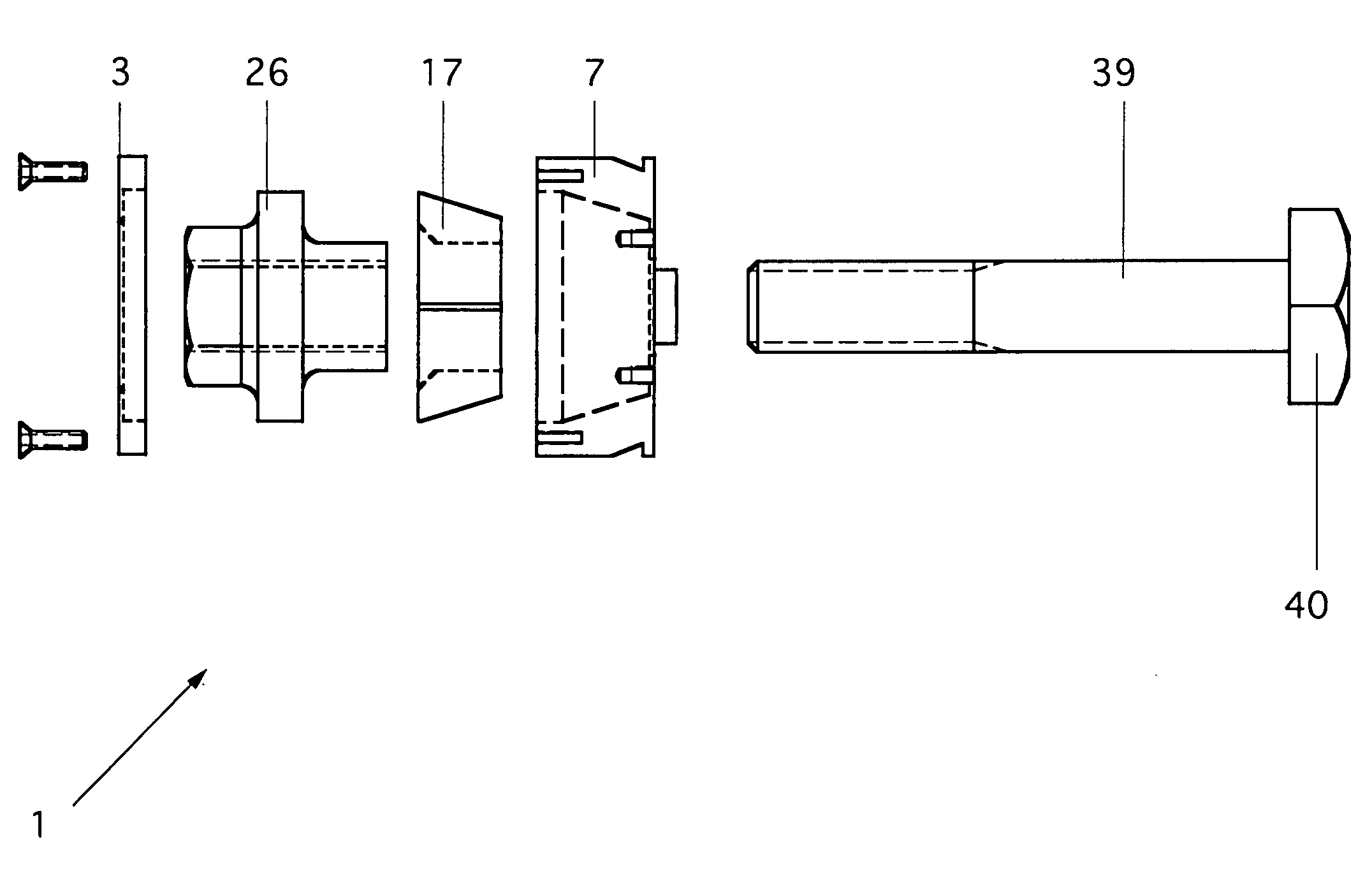
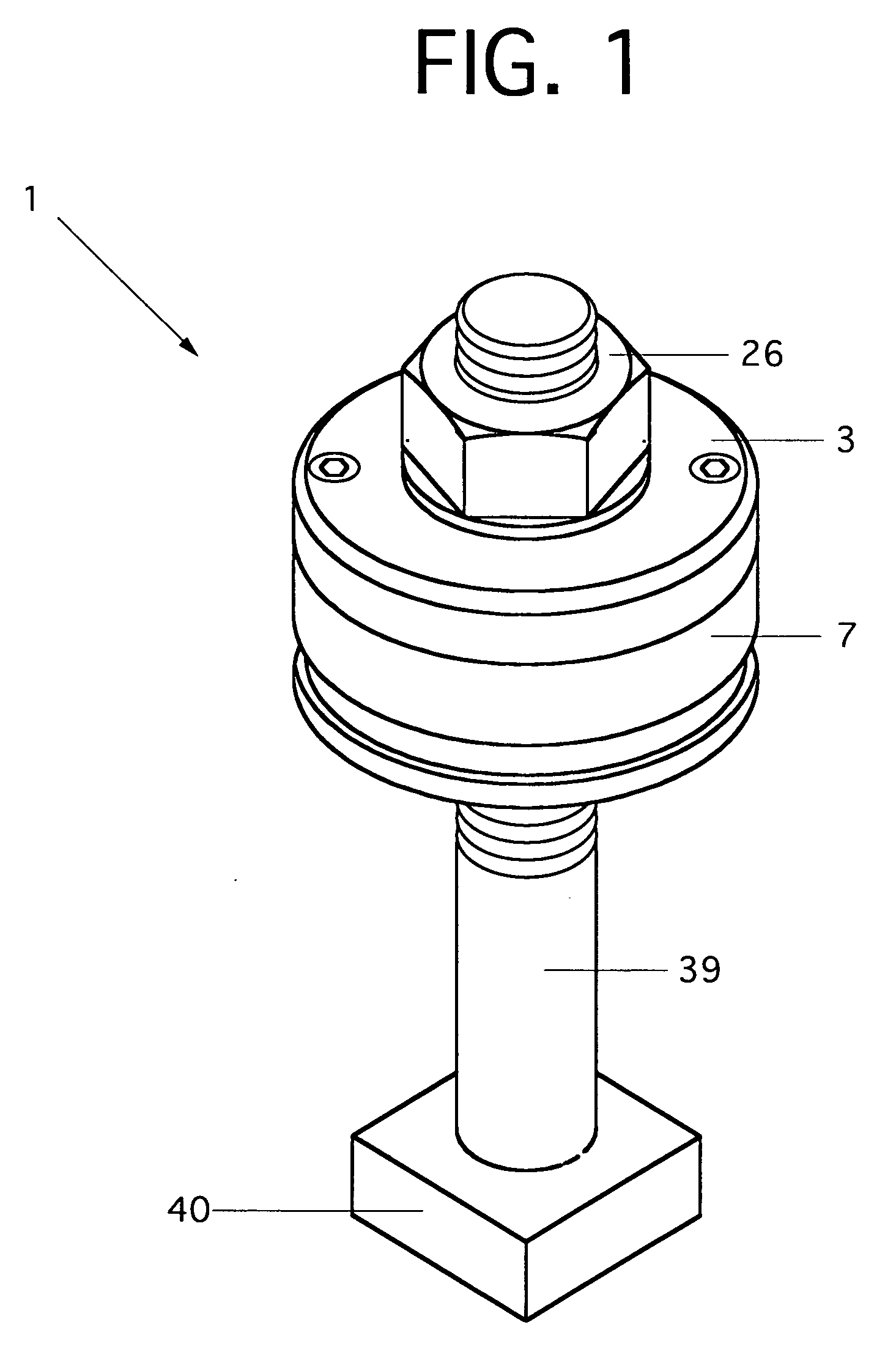
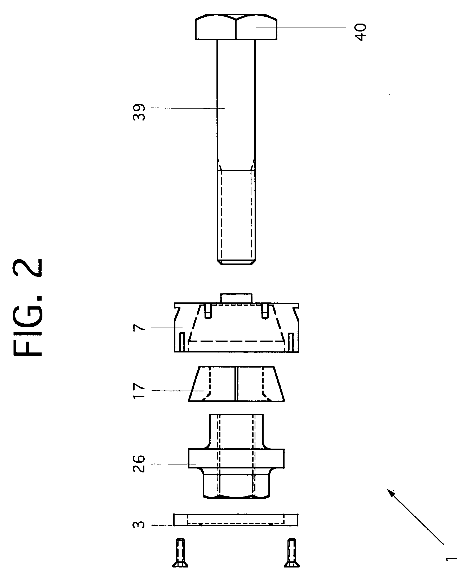
[0016]FIGS. 1-4 show a quick die change collet clamp 1 according to the present invention. The clamp 1 is used to secure a workpiece 44 such as a die shoe, die, mold, or fixture to a work surface 43 of a press 65. As shown in FIGS. 2-3, the workpiece 44 has upper and lower halves 44U and 44L. [00017] As shown in FIGS. 1 and 2, the clamp 1 comprises a stem nut 26, a topcap 3 for holding the stem nut 26 in position, a clamp bar 7 for securing the workpiece 44, and a head 40, all attached to a fastener 39. FIG. 2 further introduces a collet 17.

[0017]The process of stamping a part is shown in FIGS. 3A-3B ...


PUM


Abstract

A clamp for use in forming parts is disclosed. The clamp is durable and easily installed, thereby resulting in superior efficiency.

Description

CROSS-REFERENCE TO RELATED APPLICATIONS[0001]This application claims priority to U.S. Provisional Application No. 60 / 786,559 which was filed on Mar. 28, 2006.FIELD OF THE INVENTION[0002]This invention relates generally to a clamp for use within a press used to form parts, and more specifically to a durable and easily installed clamp which has superior efficiency.BACKGROUND OF THE INVENTION[0003]Presses used in forming parts usually require the use of clamps in order to hold the dies (workpieces) that form those parts. However, it can be difficult to install and remove these clamps, as they are subject to a significant amount of mechanical stress and thus must be carefully installed. Consequently, an improved clamp for attachment to a press used in forming parts is desired.SUMMARY OF THE INVENTION[0004]It is an object of the present invention to provide a clamp for use in a press that is durable, but can also be installed and removed quickly. It is an additional object of the present...

Claims


Application Information

Patent Timeline
IPC IPC(8): F16B37/08
CPCF16B31/04F16B39/22F16B33/002
Inventor GASKA, JAMES MICHAEL
Owner GASKA JAMES MICHAEL
Learn More