Systems and methods for deployment and operation of vertical take-off and landing (VTOL) unmanned aerial vehicles

Inactive Publication Date: 2017-08-10
SEACORP LLC
View PDF0 Cites 92 Cited by
  • Summary
  • Abstract
  • Description
  • Claims
  • Application Information

AI Technical Summary

Benefits of technology

[0016]Through dual employment of UAVs that can be impulsed using an inflator-based compressed carriage system and quadcopters, for example, this technology can be adapted to a variety of UAV platforms. A mixture of compressed carriage tube-launched UAVs (as disclosed in commonly owned U.S. Pat. No. 8,439,301, the disclosure of which is incorporated herein in its entirety) can be mixed with vertical take-off and landing (VTOL) type UAVs from the same launcher platform/trailer. The technology can provide a UAV launcher that is very modular, requires little or no maintenance and can be nearly 100% operationally ready at all times. Because of the versatility of the inflators, various UAV types, with different characteristics, can be accommodated within a single launcher. Because the system is mostly self-contained, it can be used aboard most any platform, such as ground vehicles or waterborne, e.g., sea-going vessels and can be installed, removed or modified quickly for mission-specific payloads.
[0017]In an embodiment, the system can incl

Problems solved by technology

Additionally, known UAV deployment and operation systems, such as disclosed in U.S. Pat. No. 7,089,843 to Miller et al., can req

Method used


Image

  • Systems and methods for deployment and operation of vertical take-off and landing (VTOL) unmanned aerial vehicles
  • Systems and methods for deployment and operation of vertical take-off and landing (VTOL) unmanned aerial vehicles
  • Systems and methods for deployment and operation of vertical take-off and landing (VTOL) unmanned aerial vehicles

Examples


Example

[0031]To facilitate an understanding of the principles upon which the subject matter disclosed herein is based, most illustrative embodiments are described hereinafter with reference to their implementation at a remote, land-based site. It will be appreciated that the practical applications of these principles are not limited to this particular type of implementation. Rather, they can be equally employed in any other type of UAV system operating environment where it is desired to provide for periods of deployment and operation with reduced personnel and logistics requirements.

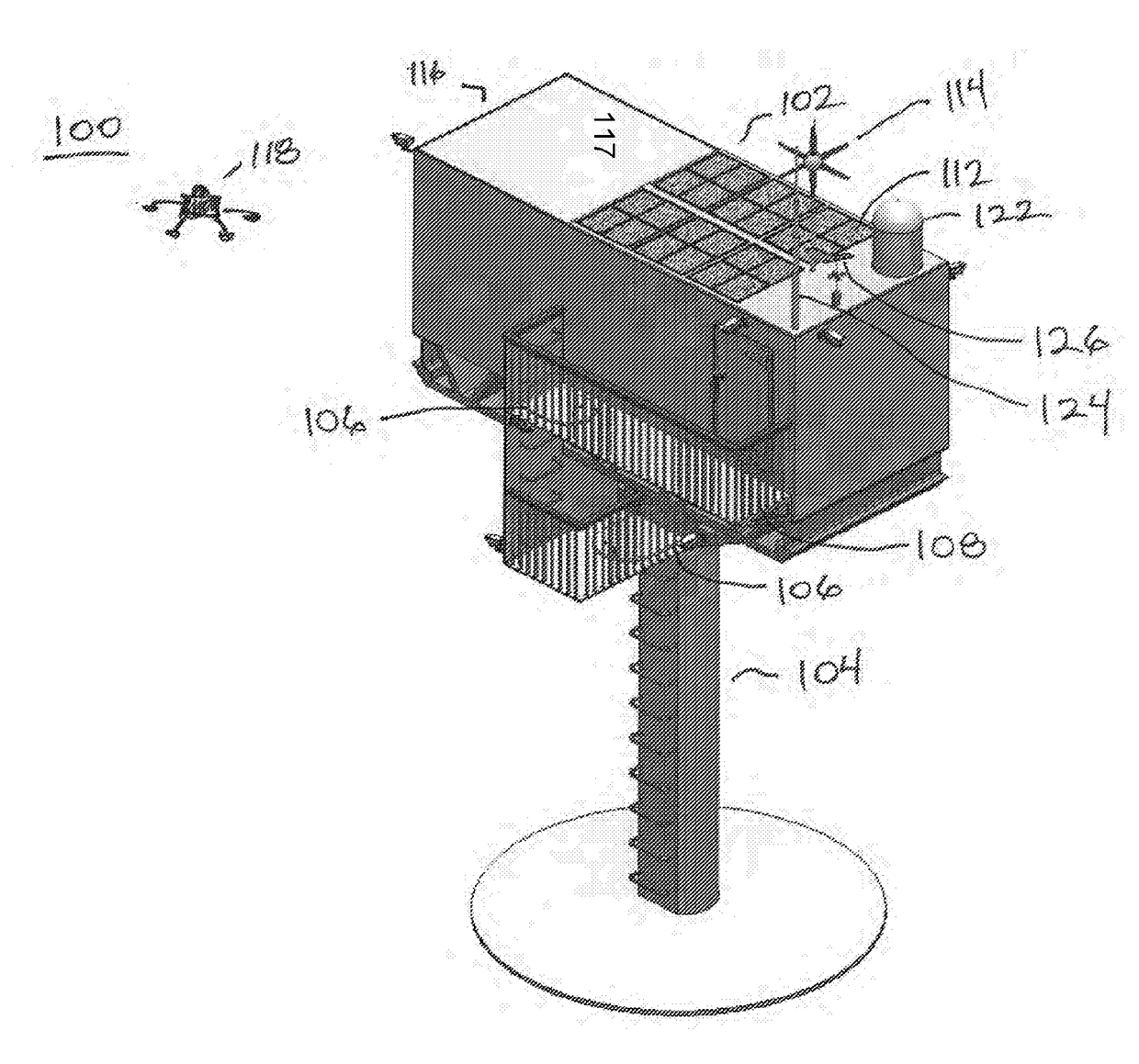
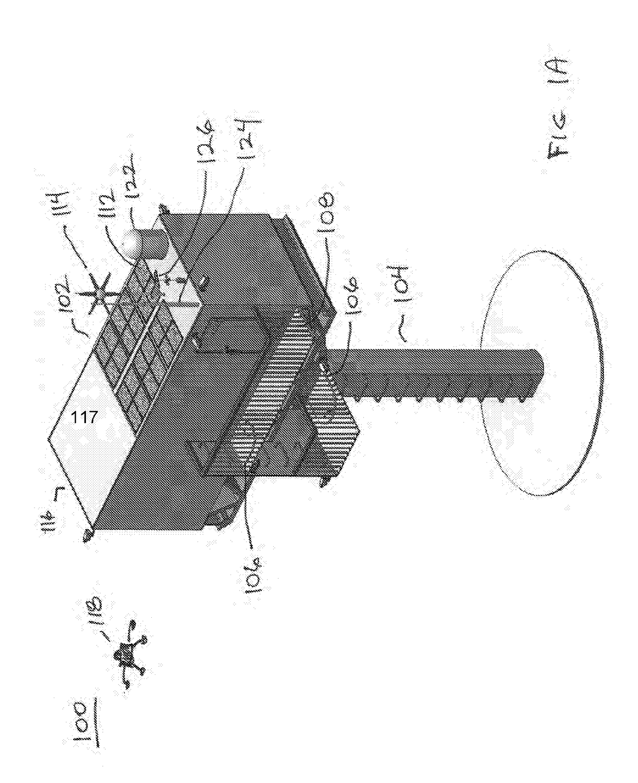
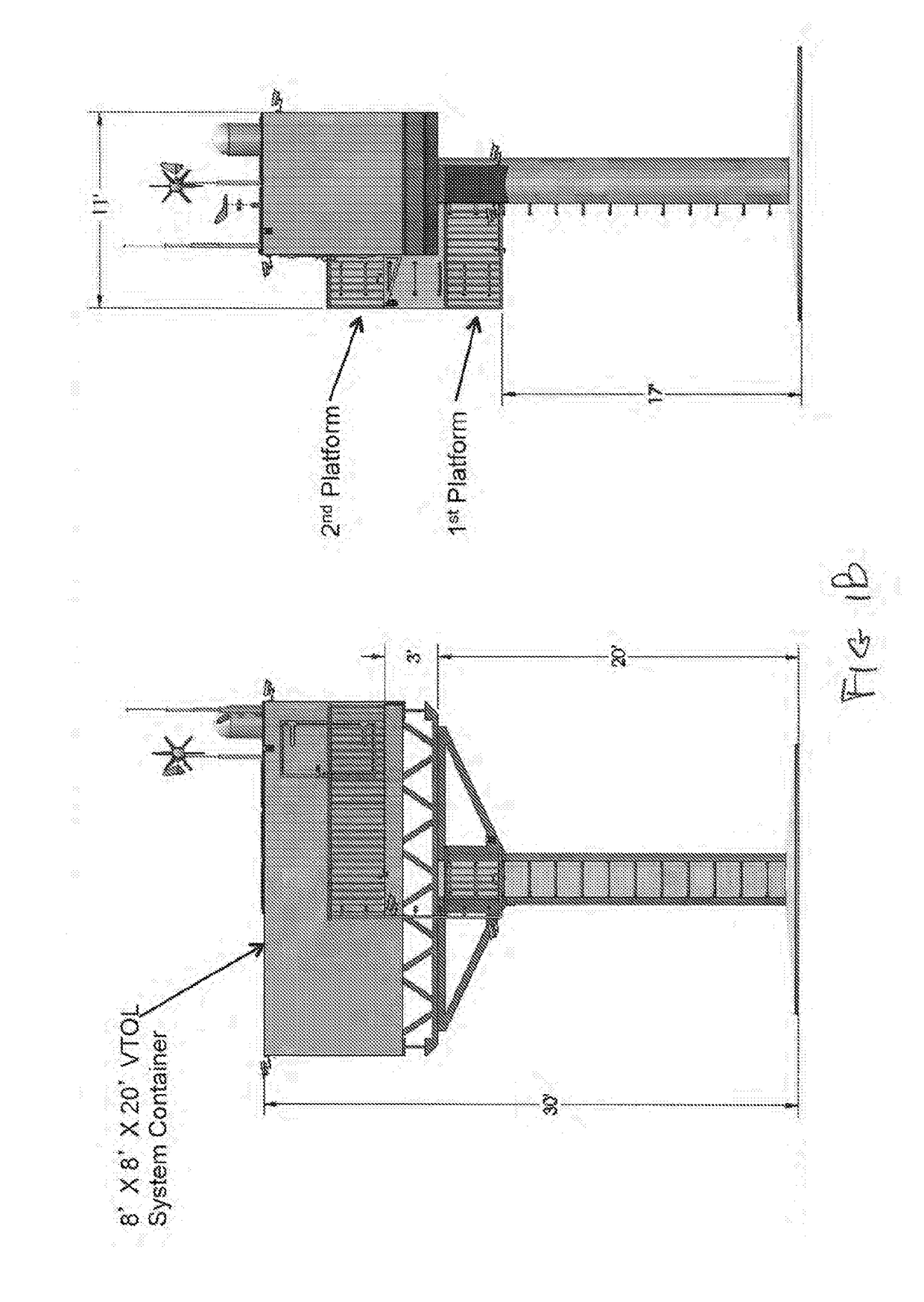
[0032]FIGS. 1A-1D show an exemplary embodiment of UAV system 100. In an embodiment, UAV system 100 can include a launcher or VTOL Hangar Cluster 102, hereinafter referred to as a VHC, comprising one or more containers, referred to herein as VTOL hangars (VH) 110 configured to house UAVs, e.g., VTOL UAV 118. In a nonlimiting embodiment, six hangars 110 can be mounted on a fixed support structure, such as tower 1...


PUM


Abstract

An unmanned aerial vehicle (UAV) system provides for UAV deployment and remote, unattended operation with reduced logistics requirements. The system includes a launcher that can include one or more containers, or hangars, configured to house vertical take-off and landing (VTOL) UAVs. The system can further include a VTOL UAV orientation and charging module configured to mechanically position a UAV within a container and facilitate electrical mating and charging of a battery in the UAV. These operations, and others, can be performed by remote command that can initiate a series of pre-programmed steps. The UAV system can further include a power generation and storage subsystem, a security subsystem, a command and control subsystem and a communications subsystem. Command, control and communications can be provided between a remote station and the UAV.

Description

CROSS-REFERENCE TO RELATED APPLICATIONS[0001]This application claims priority from U.S. Provisional Patent Application Ser. No. 62 / 063,285, filed Oct. 13, 2014, the disclosure of which is hereby incorporated by reference in its entirety.STATEMENT REGARDING FEDERALLY SPONSORED RESEARCH OR DEVELOPMENT[0002]Not Applicable.BACKGROUND[0003]Field[0004]The disclosed subject matter is generally directed to unmanned aerial vehicle (UAV) systems, and more particularly, to systems and methods that provide for the deployment and remote operation of vertical take-off and landing (VTOL) and hybrid UAVs in, for example, reconnaissance operations.[0005]Description of Related Art[0006]Known UAVs can be defined as powered aerial vehicles that do not carry a human operator, use aerodynamic forces to provide vehicle lift, can fly autonomously or be piloted remotely, can be expendable or recoverable, and can carry a lethal or nonlethal payload.[0007]There can be a wide variety of UAV shapes, sizes, conf...

Claims


Application Information

Patent Timeline
IPC IPC(8): B64F1/22B60L11/18E04H12/18B63B35/50G01S19/03E04H12/00B64C39/02B64D47/08
CPCB64F1/222B64C2201/146B60L11/1833B64D47/08B63B35/50G01S19/03E04H12/003E04H12/18B64C2201/024B64C2201/021B64C2201/042B64C2201/08B64C2201/127B64C2201/201B64C39/024B64F1/00B64F1/22B64F1/007B60L53/36H02J7/35H02J2300/40H02J2300/28Y02E10/727Y02T10/70Y02T90/12Y02T10/7072B64U10/25B64U10/13B64U50/19B64U10/10B64U80/82B64U80/70B64U80/86Y02E10/76B64U70/00B64U2101/30B64U2201/20
Inventor LUSSIER, DAVID A.DELISLE, ANDREWCHARPENTIER, BRIAN
Owner SEACORP LLC
Why Eureka
Try Eureka