Smoke exhauster mounting structure

a mounting structure and smoke exhauster technology, applied in the field of smoke exhausters, can solve the problems of not being able to easily clean or washe the motor when required, the typical smoke exhauster may no longer be detached or disengaged from the supporting surface or the supporting wall member, etc., to achieve the effect of improving the attaching or mounting structure, facilitating and facilitating the detachment or disengagement of the smoke exhauster

Inactive Publication Date: 2007-11-08
CHIANG CHI HSIUNG +2
View PDF23 Cites 35 Cited by
  • Summary
  • Abstract
  • Description
  • Claims
  • Application Information

AI Technical Summary

Benefits of technology

[0010] The primary objective of the present invention is to provide a smoke exhauster including an improved attaching or mounting structure for easily and readily attaching the smoke exhauster to a supporting surface or wall or object and for easily and readily detaching or disengaging the smoke exhauster from the supporting surface or wall or object.
[0011] In accordance with one aspect of the invention, there is provided a smoke exhauster comprising at least one rail for attaching to a supporting surface, and a housing including at least one slot formed therein, the rail is engageable into the slot of the housing for detachably attaching the housing to the rail, and for allowing the housing to be easily and quickly and readily detached or disengaged from the supporting surface for such as cleaning purposes.

Problems solved by technology

Normally, after the motor driven fan devices are stably or solidly attached or secured to the housing or the kitchen hood with the fasteners, the motor driven fan devices may no longer be detached or disengaged from the housing or the kitchen hood, such that the motor driven fan devices may not be easily cleaned or washed when required.
However, similarly, the typical smoke exhausters also may no longer be detached or disengaged from the supporting surfaces or supporting wall members or cabinets or other objects when it is required to clean or to wash the smoke exhausters.

Method used


Image

  • Smoke exhauster mounting structure
  • Smoke exhauster mounting structure
  • Smoke exhauster mounting structure

Examples


Embodiment Construction

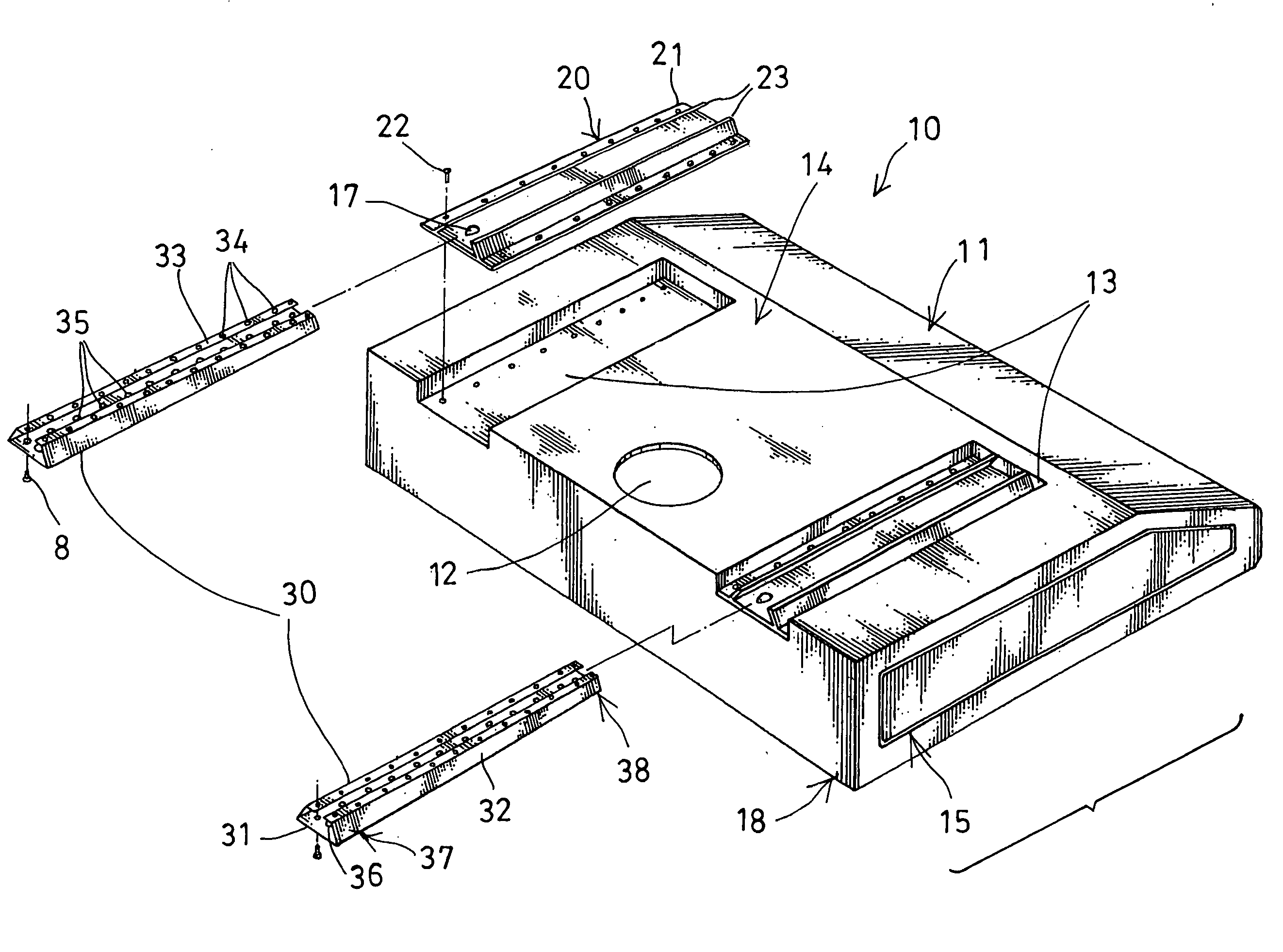
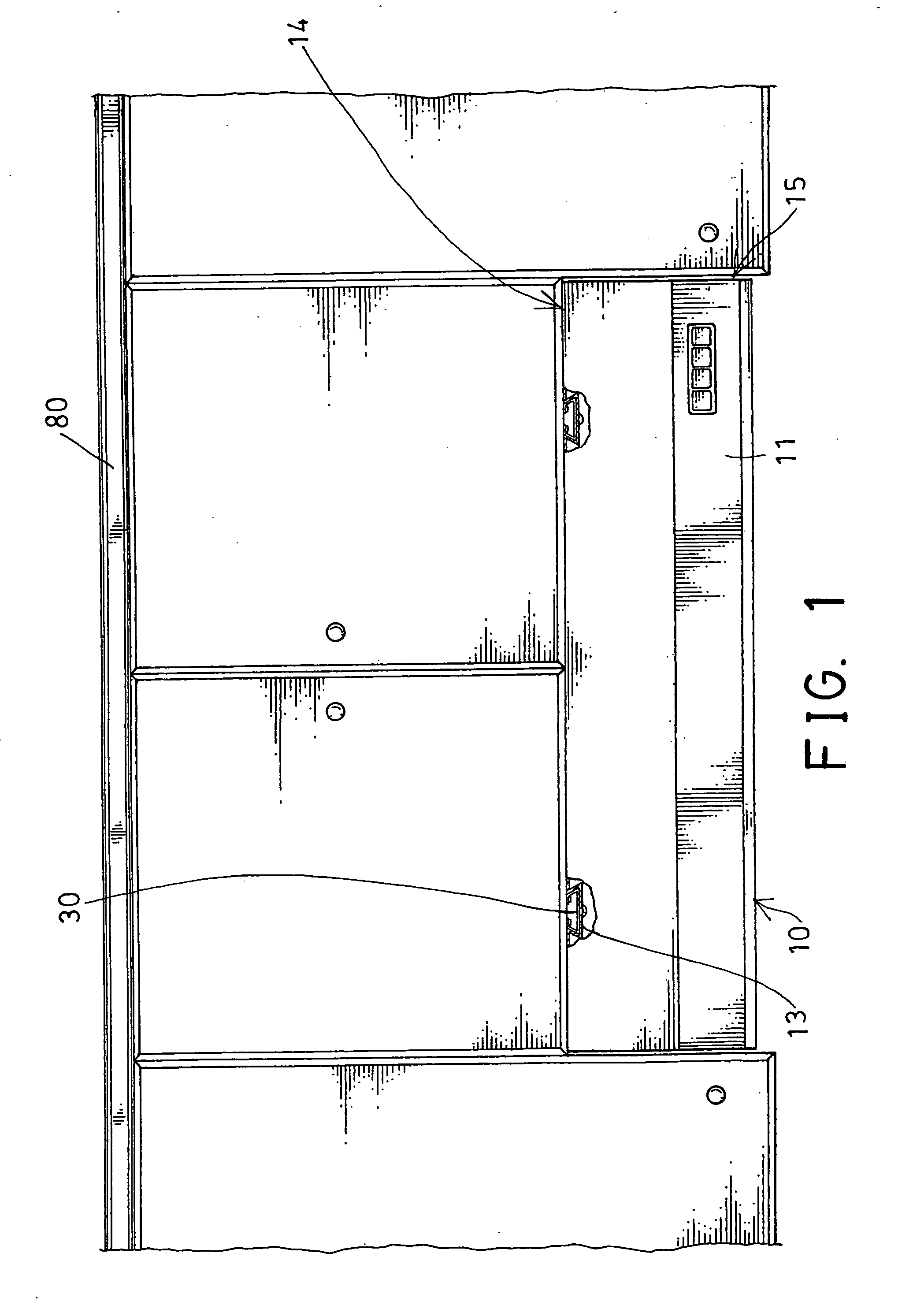
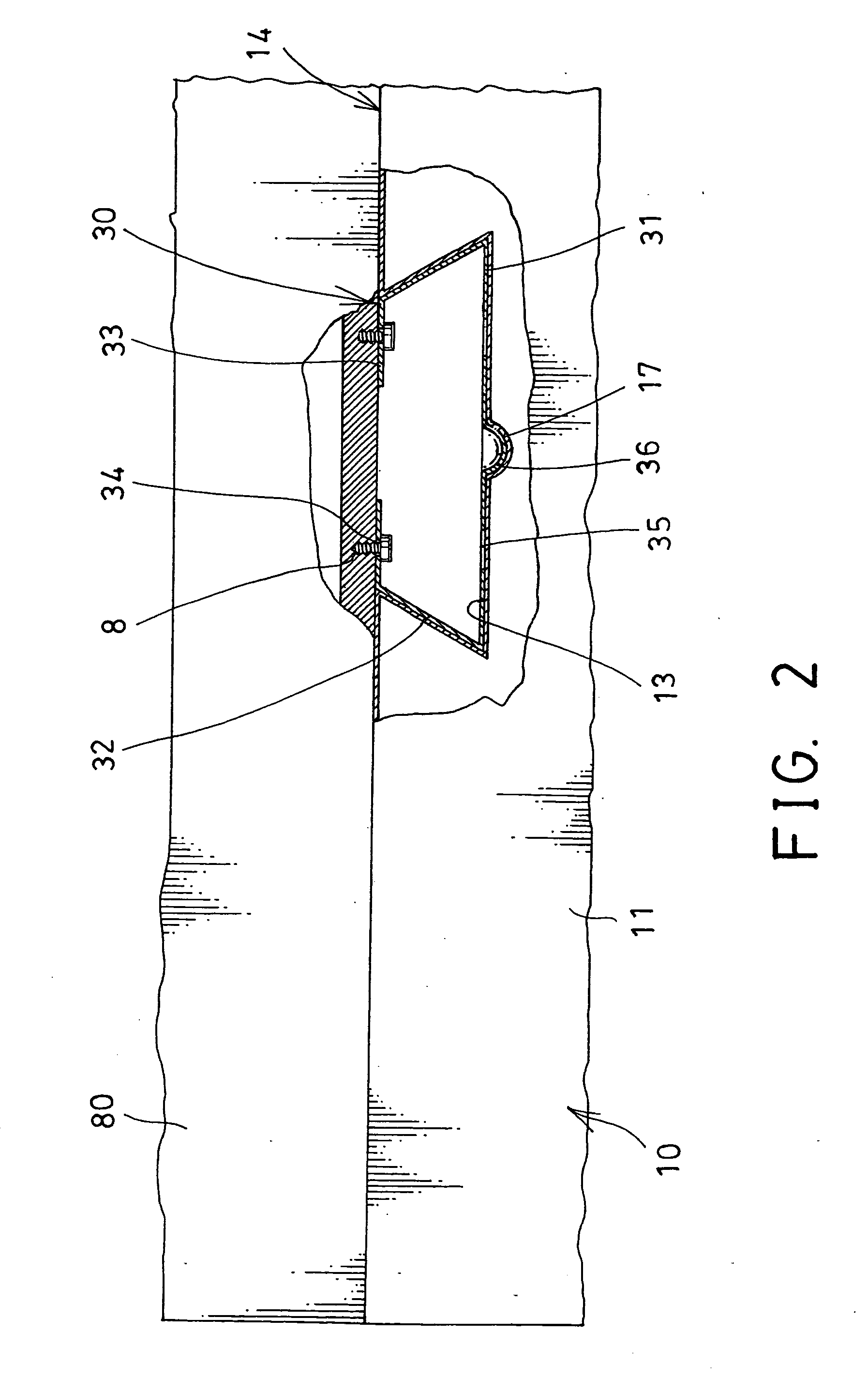
[0030] Referring to the drawings, and initially to FIGS. 1-4, a smoke exhauster 10 in accordance with the present invention comprises a box-shaped body or housing 11 which may optionally include one or more outlet ports 12 formed therein (FIGS. 4, 9, 10) for discharging the smoke or exhaust gas to the environment or to the housing buildings, for example, and may include one or more motor driven fan devices (not shown) disposed in the housing 11 for air circulating purposes and for drawing the smoke or the exhaust gas out of the housing 11. The configuration of the outlet ports 12 and the motor driven fan devices is not related to the present invention and will not be described in further details.

[0031] The housing 11 includes one or more, such as two slots 13 formed therein, such as longitudinally formed in the upper portion 14 of the housing 11 (FIGS. 1-8), or formed in the side portions 15 of the housing 11 (FIGS. 9-15), and preferably include a dovetail-shaped structure. For exa...


PUM


Abstract

A smoke exhauster includes one or more rails for attaching to a supporting surface, and a housing having one or more slots for slidably receiving the rails and for easily and readily and detachably attaching the housing to the rail or the supporting surface. The rail includes an anchoring member, such as a projection extended from the rail, and the housing includes another anchoring member, such as a depression formed in the housing for engaging with the projection and for detachably anchoring the housing to the rail. The rail includes one or more securing panels for securing to the supporting surface with fasteners, and a base panel having a number of apertures for engaging the fasteners.

Description

BACKGROUND OF THE INVENTION [0001] 1. Field of the Invention [0002] The present invention relates to a smoke exhauster, and more particularly to a smoke exhauster including an improved mounting structure for easily and readily attaching the smoke exhauster to a supporting surface or wall or object and for easily and readily disengaging or detaching the smoke exhauster from the supporting surface or wall or object. [0003] 2. Description of the Prior Art [0004] Typical smoke exhausters comprise a box-shaped body or housing having an outlet port for discharging the smoke or exhaust gas to the environment, and one or more motor driven fan devices disposed in the housing for air circulating purposes and for drawing the smoke or exhaust gas out of the housing. [0005] For example, U.S. Pat. No. 4,146,016 to Bowen, Jr. et al. discloses one of the typical smoke exhausters comprise a box-shaped body or housing for being disposed in a kitchen hood and one or more motor driven fan devices dispo...

Claims


Application Information

Patent Timeline
Patent Type & Authority Applications(United States)
IPC IPC(8): F24C15/20
CPCF24C15/2071
Inventor CHIANG, CHI-HSIUNGCHIANG, I-WENCHIANG, CHAO-CHENG
Owner CHIANG CHI HSIUNG
Why Eureka
Try Eureka