Helical taper induced vortical flow turbine

US20070258806A1Active Publication Date: 2007-11-08HART JAMES R

Image

  • Helical taper induced vortical flow turbine
  • Helical taper induced vortical flow turbine
  • Helical taper induced vortical flow turbine

Examples


Example

DETAILED DESCRIPTION OF THE DRAWINGS

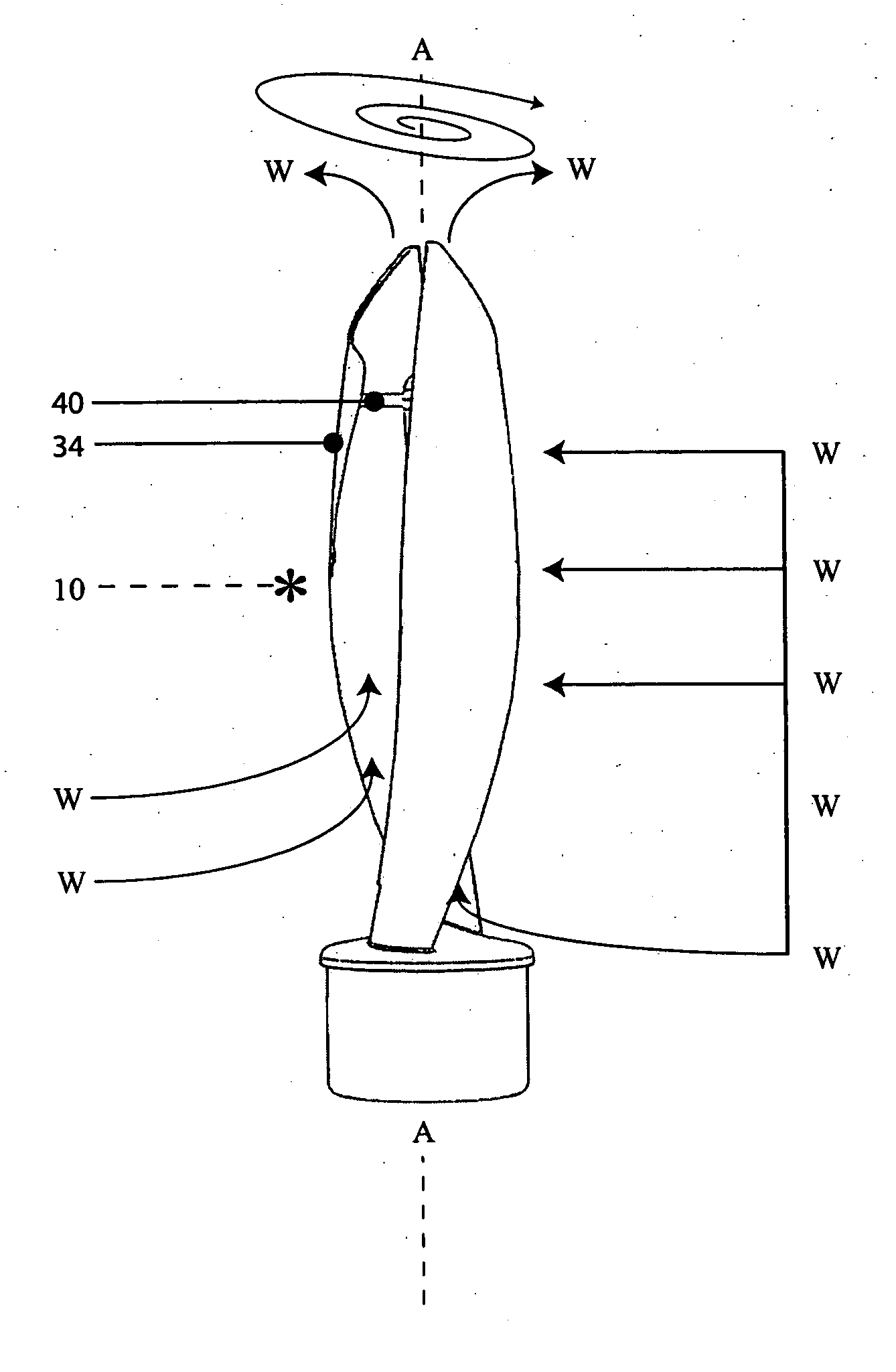
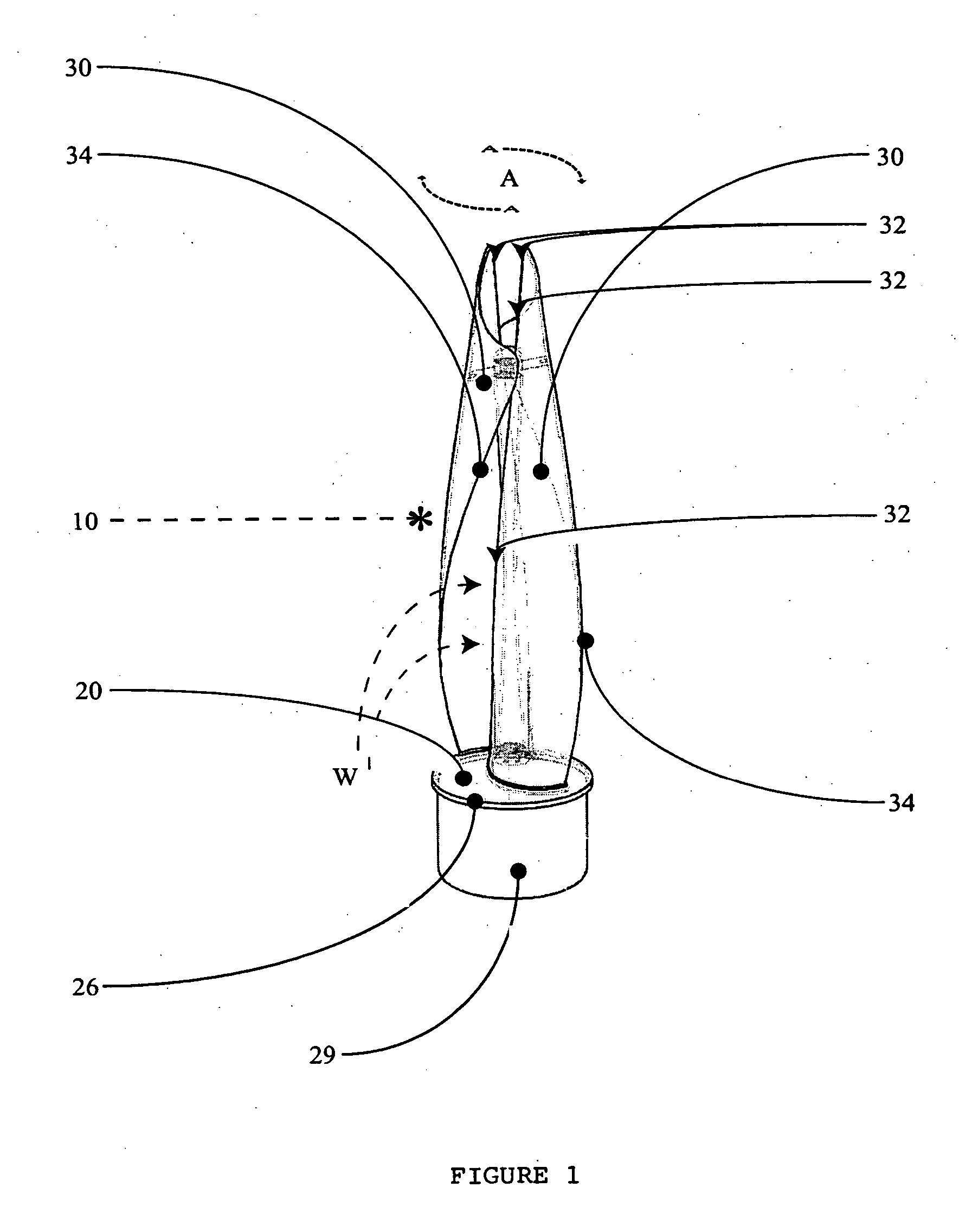
[0073] The present invention provides a novel turbine generator system 10. As seen in FIG. 1, turbine generator system 10 includes a rotatable base 20, and a plurality of rotor vanes 30 extending from rotatable base 20. Each of rotor vanes 30 has a helical tapered inner surface 32 and a helical tapered outer surface 34. The top ends of rotor vanes 30 may optionally be attached together by a member 40 (positioned at the top of a mast 35).

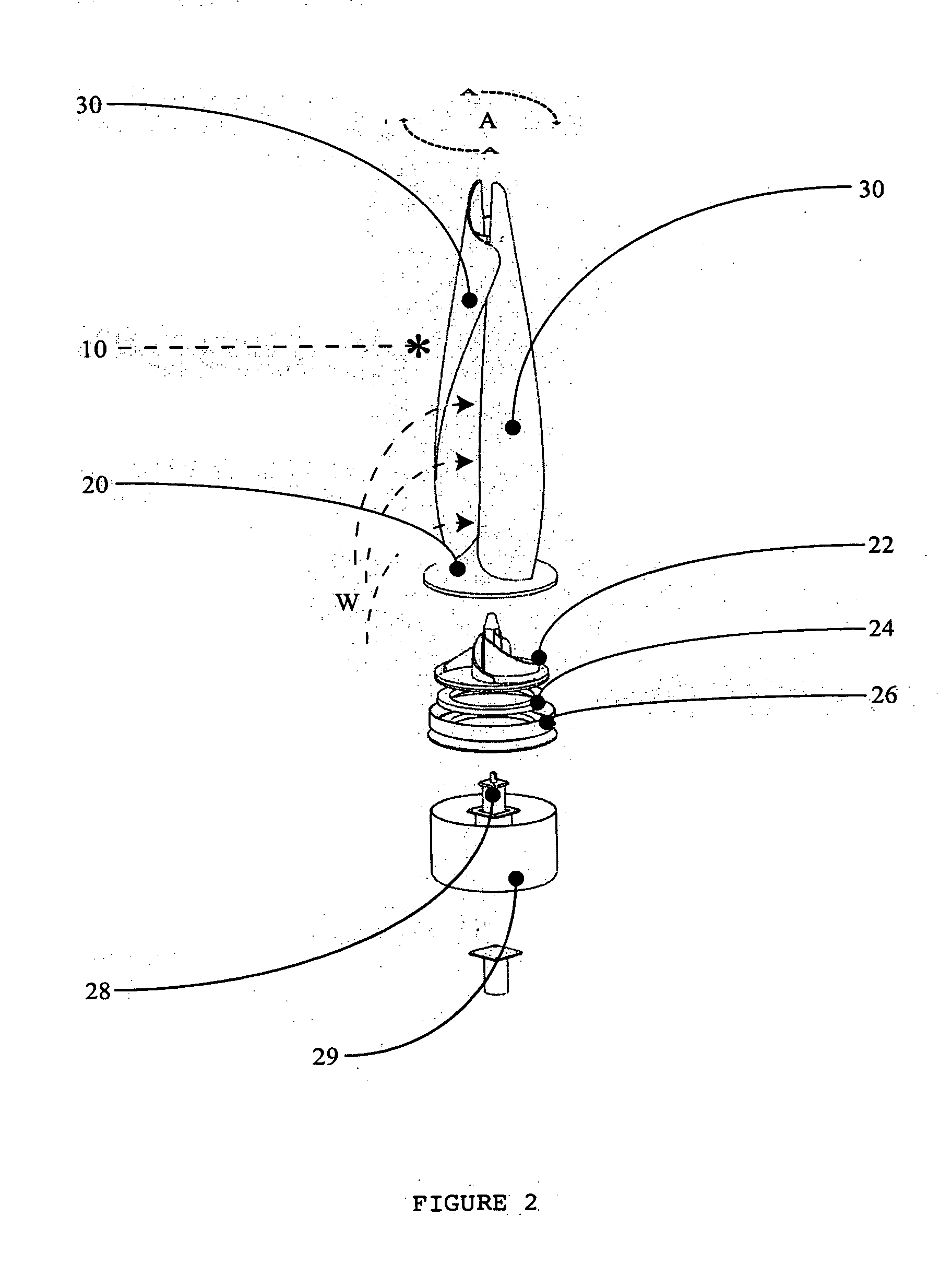
[0074]FIG. 2 is an exploded view of one embodiment of the invention showing additional components disposed under base 20. Specifically, a weighted flywheel base 22, an optional plurality of magnetic repulsion rotor / base support surfaces 24, cover extension 26, geared electric generator motor 28 and cover 29 are shown.

[0075] The operation of turbine generator system 10 can be understood by viewing the remaining FIGS. 3 to 11 together, as follows.

[0076] FIGS. 3 to 5 illustrate the turbine generator system 10 rota...


PUM


Abstract

A turbine generator system, having: a rotatable base; and a plurality of rotor vanes extending from the rotatable base, wherein each of the rotor vanes have helical tapered inner and outer surfaces, and wherein each of the rotor vanes is curved to catch flow perpendicular to the axis of rotation of the rotatable base and to direct the flow into a vortical flow between the inner surfaces of the rotor vanes.

Description

TECHNICAL FIELD [0001] The present invention relates to wind turbine electric generator systems. BACKGROUND OF THE INVENTION [0002] (a) General Background [0003] A large number of existing turbine vane rotor designs take advantage of mechanical energy conversion processes using gases and fluid movement. Broadly speaking, there are turbine rotors comprised of one or more vanes, that rotate about a horizontal axes and also similar designs that rotate about a vertical axes. For example: “turbine rotor vane designs can be found in use on wind electrical generators and in various fluid pump designs for the work they produce because of the presence of kinetic energy that can be extracted from fluid and gas flows”. [0004] Familiar “wind turbine rotor vane designs” are comprised of two common opposing axes oriented counterparts. They convert force applied to the “rotor vanes” and spin on a horizontally oriented axis (horizontal axis machine types; hereinafter referred to as “HAWT”), or vert...

Claims


Application Information

Patent Timeline
08 Nov 2007
Publication
US20070258806A1
IPC
F03B3/12
CPC
F03B17/063; F03D3/005; F03D3/061; Y10S415/907; Y02E10/28; Y02E10/74; F05B2210/16; F05B2250/25
Inventors
HART, JAMES R.