

Deflectable sheath handle assembly and method therefor
a technology of deflectable sheaths and handle assemblies, which is applied in the direction of catheters, medical devices, other medical devices, etc., can solve the problems of increased fatigue of pull wires, difficulty in accurately positioning catheters in certain body vessels, and awkward mechanisms or the use of two hands
- Summary
- Abstract
- Description
- Claims
- Application Information
AI Technical Summary
Problems solved by technology
Method used
Image

Examples
Embodiment Construction
[0015] In the following detailed description, reference is made to the accompanying drawings, which form a part hereof, and in which is shown by way of illustration specific embodiments in which the invention may be practiced. These embodiments are described in sufficient detail to enable those skilled in the art to practice the invention, and it is to be understood that other embodiments may be utilized and that structural changes may be made without departing from the spirit and scope of the present invention. Therefore, the following detailed description is not to be taken in a limiting sense, and the scope is defined by the appended claims.
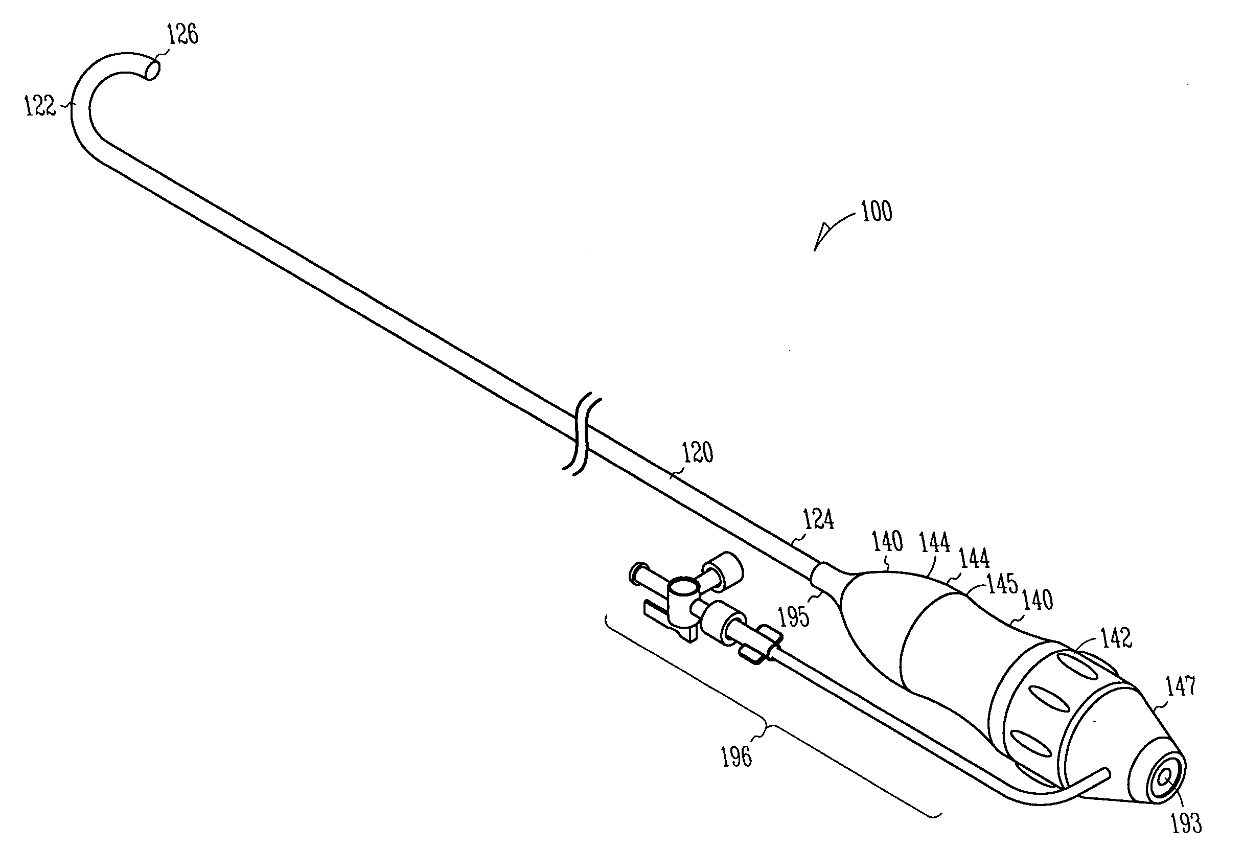
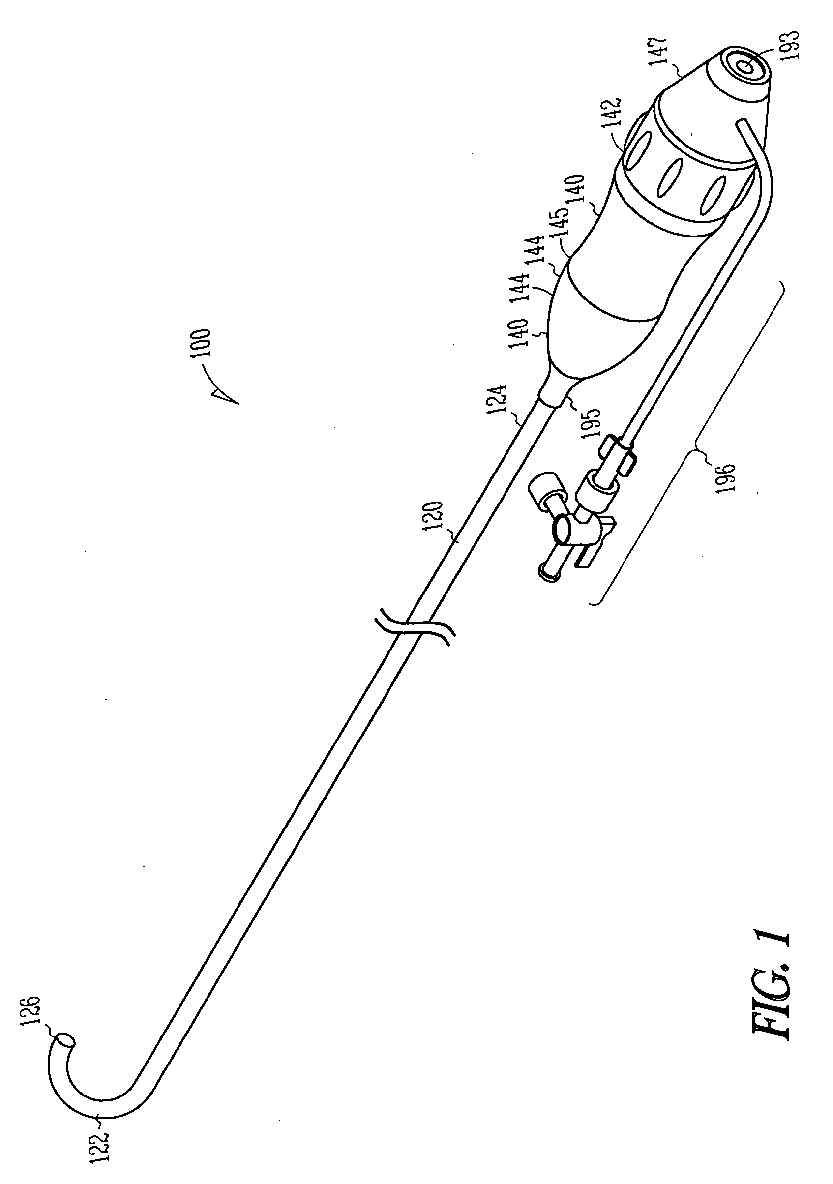
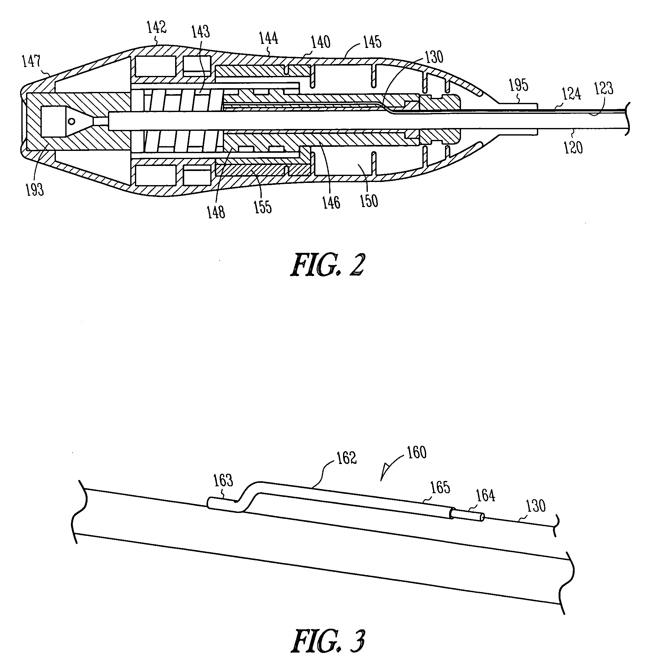
[0016] A deflectable sheath assembly 100 is illustrated in FIGS. 1 and 2, and generally includes a deflectable body 120, a housing assembly 140, and a pullwire 130. The deflectable body 120 extends from a distal end portion 122 to a proximal end portion 124, and includes a passage 123 therethrough. The passage 123 allows for instruments to be...
PUM
 Abstract
Description
Claims
Application Information