
Backlight module and method of making the module

a backlight module and module technology, applied in the direction of instruments, lighting and heating apparatuses, measurement apparatus components, etc., can solve the problems of large volume and large size of crt display devices

Inactive Publication Date: 2007-11-15
AVAGO TECH WIRELESS IP SINGAPORE PTE
View PDF8 Cites 112 Cited by
  • Summary
  • Abstract
  • Description
  • Claims
  • Application Information

AI Technical Summary

Problems solved by technology

However, CRT technology requires a large volume, and consequently, CRT display devices are large in size.

Method used


Image

  • Backlight module and method of making the module
  • Backlight module and method of making the module
  • Backlight module and method of making the module

Examples


Embodiment Construction

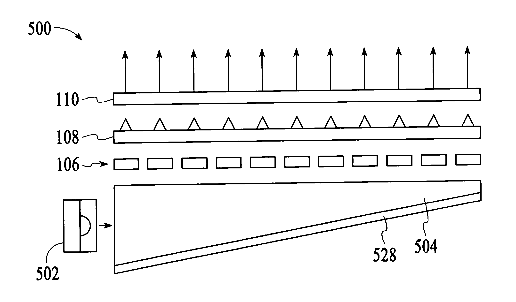
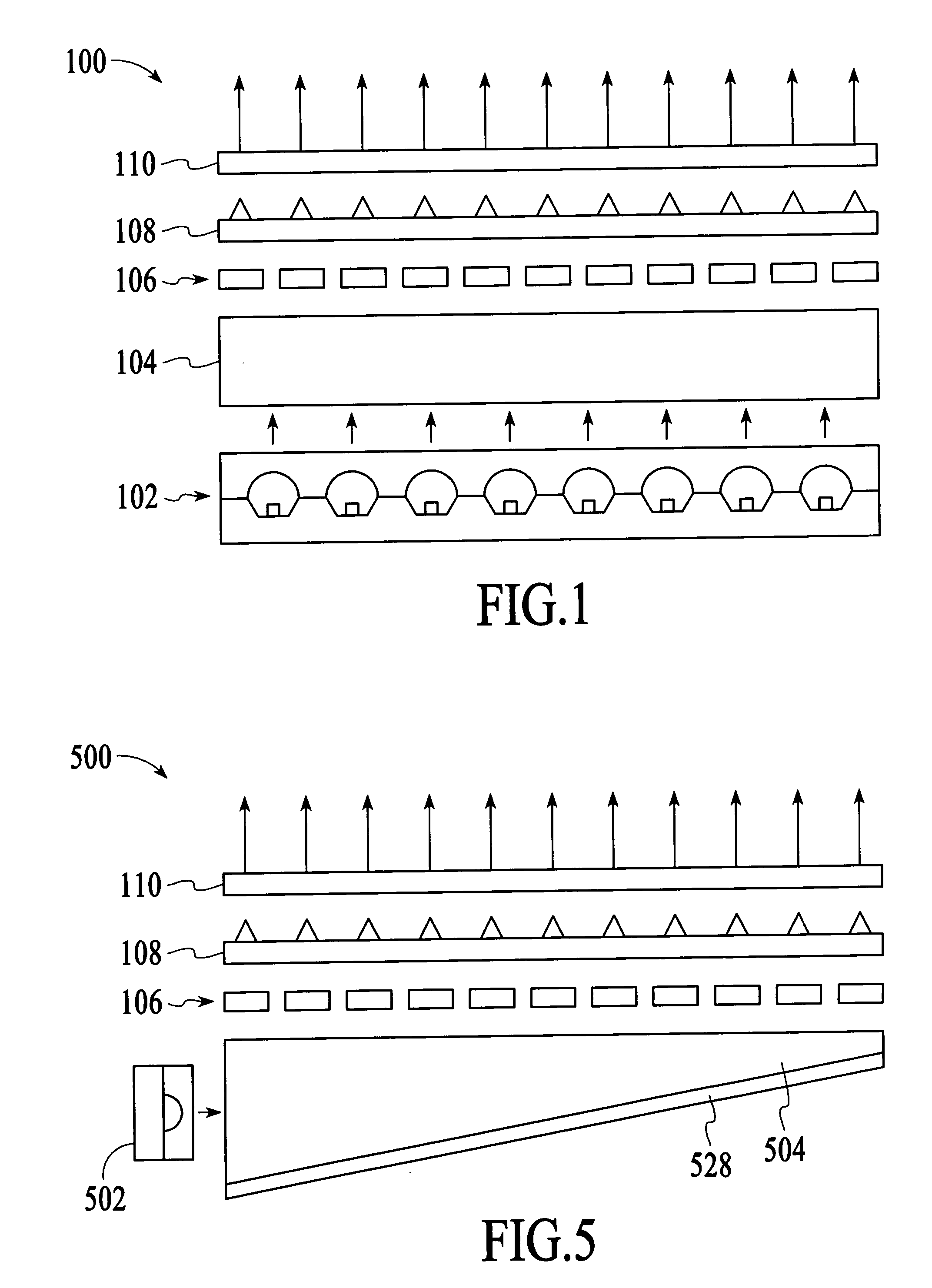
[0015] With reference to FIG. 1, a backlight module 100 in accordance with an embodiment of the invention is described. The backlight module 100 operates to provide illumination for a display device, such as a liquid crystal display (LCD). The backlight module 100 can provide illumination with improved luminance uniformity and improved light efficiency compared to conventional backlight modules that use Cold Cathode Fluorescent Lamps (CCFLs). In addition, the backlight module 100 can provide a wide light emitting area for use in large sized display devices. Furthermore, the manufacturing cost of the backlight module 100 is relatively inexpensive when compared to other comparable backlight modules.

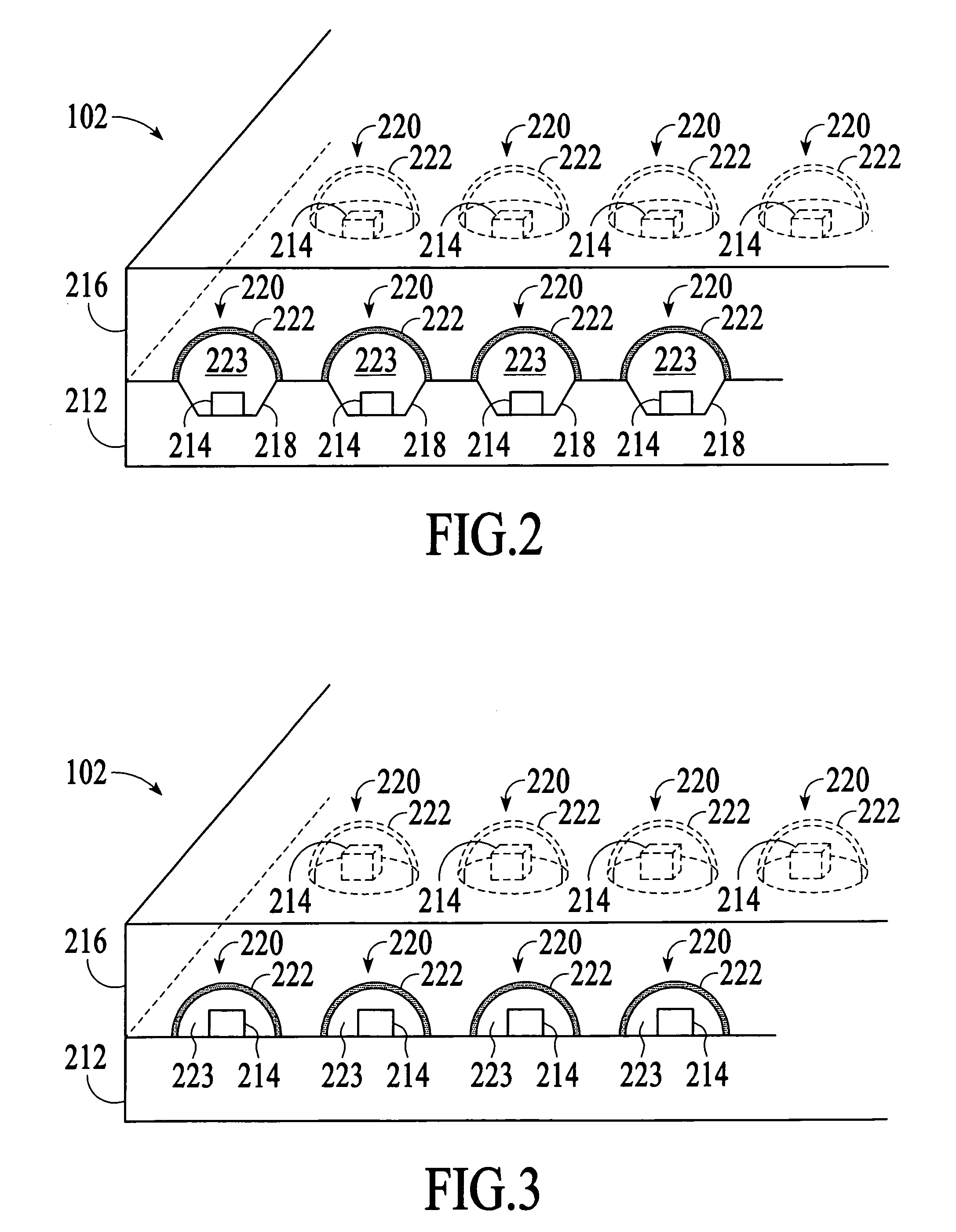
[0016] In this embodiment, the backlight module 100 is a direct-type backlight module. The components of the backlight module 100 are shown in FIG. 1, which is an exploded diagram of the module. The backlight module 100 includes a light source device 102, a light guide panel 104, a diffusi...


PUM


Abstract

A backlight module and method of making the module uses a light panel and a light source device. The light source device includes a substrate on which light-emitting dies are mounted and an encapsulation plate with depressions, which is attached to the substrate such that the depressions are positioned over the light-emitting dies.

Description

BACKGROUND OF THE INVENTION [0001] In the past, cathode ray tube (CRT) technology was commonly used in electronic display devices. However, CRT technology requires a large volume, and consequently, CRT display devices are large in size. Therefore, many flat panel display technologies have been developed, such as liquid crystal display (LCD), plasma display panel (PDP) and field emission display (FED) technologies. Of these technologies, the LCD technology is attracting attention in the field of full-color display devices. [0002] An LCD display device is a planar display with low power consumption. In comparison with a CRT display device with the same screen size, an LCD display device is much lighter and smaller with respect to space occupation. Furthermore, unlike the curved screen in the CRT display devices, an LCD display device has a planar screen. With these advantages, LCD display devices have been widely used in various products, including palm calculators, electronic diction...

Claims


Application Information

Patent Timeline
IPC IPC(8): G01D11/28
CPCG02F1/133603G02F2001/133614G02F1/133621G02F1/133614
Inventor CHUA, JANET BEE YIN
Owner AVAGO TECH WIRELESS IP SINGAPORE PTE
Features
  • Generate Ideas
  • Intellectual Property
  • Life Sciences
  • Materials
  • Tech Scout
  • Unparalleled Data Quality
  • Higher Quality Content
  • 60% Fewer Hallucinations
Learn More