Foldable conveyor with automatic tensioning device

a conveyor and automatic technology, applied in the direction of conveyors, transportation and packaging, etc., can solve the problems of affecting the unfolding operation, and the belt lacks appropriate tension, so as to reduce the set up time, and facilitate the unfolding operation.

Inactive Publication Date: 2007-11-22
JORGENSEN CONVEYORS +1
View PDF27 Cites 11 Cited by
  • Summary
  • Abstract
  • Description
  • Claims
  • Application Information

AI Technical Summary

Benefits of technology

[0006]It is desirable to provide a foldable conveyor which in a folded state is more compact than its unfolded state and thus cheaper to ship. Such a foldable conveyor should be easy to unfold and easy to set up at its destination. A foldable conveyor having a simple pivot hinge meets these requirements. Shipping such a foldable conveyor with an installed belt also reduces set up time. However, a foldable conveyor having a simple pivot hinge will have a partial gap between the horizontal loading section and the inclined section in the folded state, such that without an automatic tensioning device, as the conveyor is unfolded, the belt lacks appropriate tension and can bunch up in the area of the gap and interfere with the unfolding operation. Thus one object of the present invention is to provide a foldable conveyor which can be shipped with an installed belt and which includes a tensioning device which operates to automatically tension the belt and prevent the belt from interfering with an unfolding operation. Such a foldable conveyor can be shipped with the belt installed and is easily unfolded and assembled at its destination.

Problems solved by technology

However, a foldable conveyor having a simple pivot hinge will have a partial gap between the horizontal loading section and the inclined section in the folded state, such that without an automatic tensioning device, as the conveyor is unfolded, the belt lacks appropriate tension and can bunch up in the area of the gap and interfere with the unfolding operation.

Method used


Image

  • Foldable conveyor with automatic tensioning device
  • Foldable conveyor with automatic tensioning device
  • Foldable conveyor with automatic tensioning device

Examples


Embodiment Construction

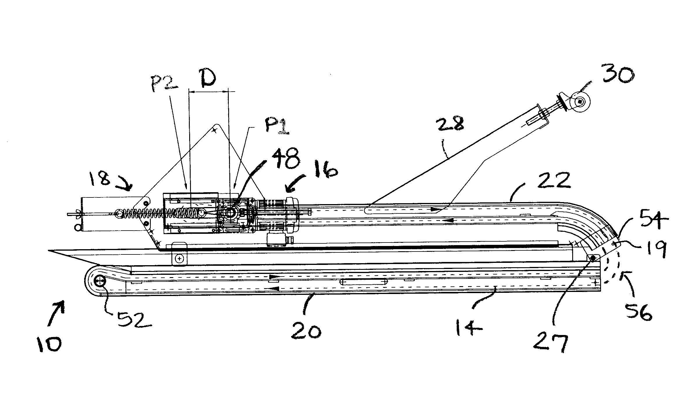
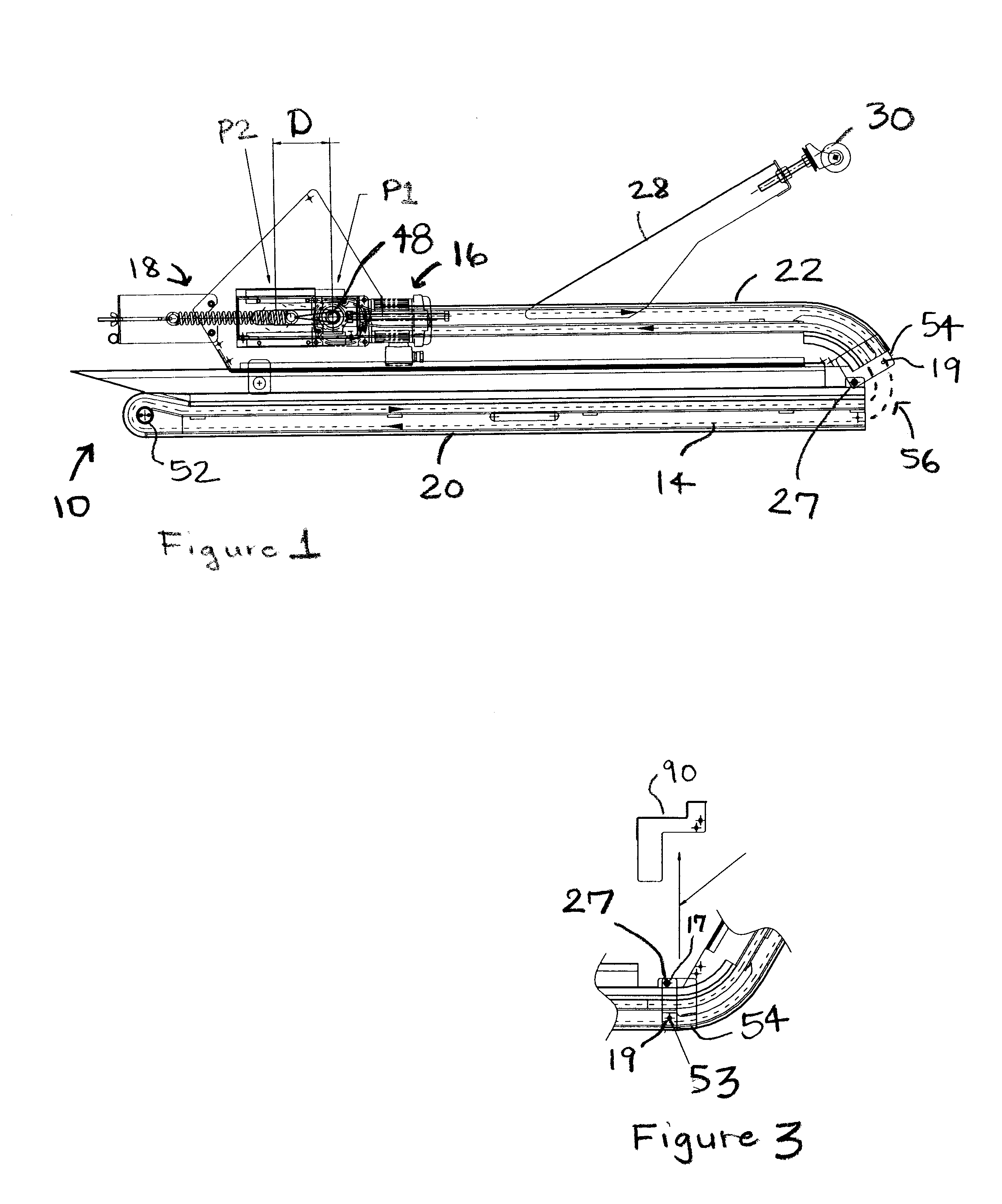
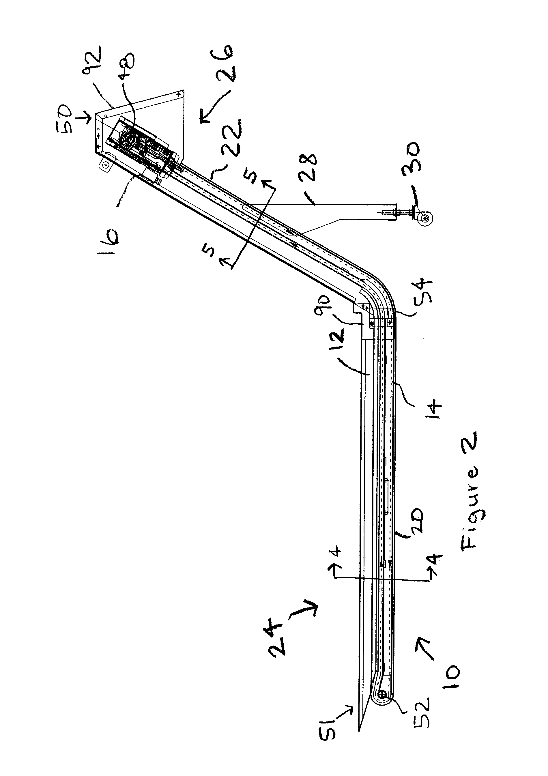
[0017]Referring now to the drawings, wherein like reference characters represent corresponding elements throughout the several views, and more specifically to FIGS. 1 and 2, the present invention will be described in the context of an exemplary foldable conveyor 10. The conveyor 10 is shown in FIG. 1 in a folded state and with an installed continuous belt 14 (indicated by dashed lines) and an automatic tensioning device 18. The conveyor 10 in the folded state can be supported on and bound to a pallet and placed inside a shipping container for shipping to a desired destination. FIG. 2 illustrates the conveyor 10 in an unfolded state in which the tensioning device 18 shown in FIG. 1 has been removed and in which the conveyor 10 is operable to convey material on the belt 14 from a loading area 24 to a discharge area 26.

[0018]Conveyor 10 generally includes a conveyor frame 12 for supporting the continuous belt 14 and a drive mechanism 16 for driving the continuous belt 14 during operati...


PUM


Abstract

A foldable conveyor includes a conveyor frame having a horizontal section and an inclined section pivotable with respect to the horizontal section to permit the conveyor to be in a compact folded state as well as an unfolded operational state. The conveyor includes a continuous belt such as a hinged metal belt which is movable to transport material from a loading area to a discharge area. A tensioning device provides appropriate tension on the belt to prevent the belt from interfering in an unfolding operation.

Description

CROSS-REFERENCE TO RELATED APPLICATIONS[0001]This application claims priority to U.S. provisional patent application Ser. No. 60 / 802363, filed May 22, 2006, and titled “Foldable Conveyor System”.STATEMENT REGARDING FEDERALLY SPONSORED RESEARCH OR DEVELOPMENT[0002]Not applicable.FIELD OF THE INVENTION[0003]The present invention relates generally to a foldable conveyor, and in particular to a foldable conveyor having an automatic tensioning device which permits the conveyor to be shipped with an installed belt and unfolded without difficulty.BACKGROUND OF THE INVENTION[0004]Flexible metal belt conveyors are used for many purposes in manufacturing and industrial fields for moving machine parts being treated or processed, moving metal “chips” generated in machining processes, or moving raw materials such as sand, gravel, ores or the like. One type of known metal belt conveyor includes a lower horizontal loading section, an inclined section, and optionally an elevated horizontal section....

Claims


Application Information

Patent Timeline
Patent Type & Authority Applications(United States)
IPC IPC(8): B65G21/10
CPCB65G23/44B65G21/14
Inventor WALSH, JOSEPH M.WEBERS, GARY E.
Owner JORGENSEN CONVEYORS
Why Eureka
Try Eureka