Modular sanitation tray systems

a sanitation tray and module technology, applied in the field of sanitation trays, can solve the problems of increasing drying time, reducing proper sanitation, and insufficient removal of particulate matter and blood borne pathogens, so as to improve sanitation capabilities, reduce shipping costs, and reduce drying time

Inactive Publication Date: 2016-06-14
ABENE MICHAEL A
View PDF29 Cites 1 Cited by
  • Summary
  • Abstract
  • Description
  • Claims
  • Application Information

AI Technical Summary

Benefits of technology

[0013]Accordingly, it is a primary object of the present invention to overcome the aforementioned problems and disadvantages of the related art. Another object of the present invention is to provide a modular, stacking sanitation tray system having enhanced sanitation capabilities and decreased drying time as compared to related art stacking sanitation tray systems, and which provides quick assembly, user customization, decreased shipping costs, and the ability to sanitize instruments of differing sizes at the same time. It should be understood that the present invention is capable of use in equipment that is capable of use in both sanitizing and sterilizing laboratory equipment. The terms can be used interchangeably or to define levels of disinfection. For purposes of clarification, when the term “sanitize” is used to describe the system, it is contemplated within the current invention to provide a tray system that is capable of both “sterilizing” and “sanitizing” laboratory equipment, e.g. removing contaminants and cleaning and / or a “total kill” of all pathogens.
[0014]The present invention provides a modular, user-customizable storage, transportation and sanitation tray system for equipment. It provides a safe, effective, convenient, and economical system to accommodate a number of different types of equipment of various shapes and sizes in need of sanitization. A single unit of this system includes a rack, corners, sides, and a plurality of dowels. A single unit of this system may optionally include a plurality of handles, a plurality of holders, and / or a plurality of covers. These units may function as a single unit or a plurality of these units can function in concert to provide a user with any desired configuration of trays to her sanitation needs.
[0015]Within a single unit, the corners and sides are attached to each other with the dowels. The dowels may connect a corner piece to another corner piece, a side piece to a corner piece, and / or a side piece to another side piece in a horizontal configuration to permit the user to create a tray system that best serves his or her sanitation needs. A rack may be removably positioned in grooves within the corner or side piece(s). Each corner or side piece may also include a male and / or female coupling element that allows the user to stack the unit on top of another unit. At least one of the surfaces may have any number of holders for securing instruments horizontally or vertically. The holders may be positioned within the system to accommodate the equipment in need of sanitization. A single unit may also attach to another unit to form a system wherein the user specifies the overall shape, height, length, and / or width of the system. In an assembled configuration, equipment within the tray system is stabilized for easy transport into and out of the sanitation machine or in and around the facility at which it is used.
[0016]Accordingly, it is an object of this invention to provide a sanitation tray system which is for medical, laboratory, or industrial equipment and which is customized to the individual user's specifications. Still another object of this invention is to provide a sanitation tray system that minimalizes drying time and the potential for pooled sterilants, accumulation of particulate matter and / or blood borne pathogens, and maximizes sanitation of the instrument by using as little solid matter in its construction. A further object of this invention is to provide a method of sanitizing instruments that can be arranged vertically and horizontally. Still another object of this invention is to provide a sanitation tray system that is economical to manufacture, easy and economical to ship, easy to use, modular, stackable, and is readily assemblable and disassemblable. Other features, objects, and advantages of the present invention will become apparent from the following description of a preferred embodiment of the invention taken in conjunction with the accompanying drawings.

Problems solved by technology

Current sanitization trays are typically one-piece constructions with vent holes that do not have sufficient porosity to permit heat, steam, and other sterilants to permeate the system thoroughly.
This also permits sterilants to pool around the instruments within the system, which decreases proper sanitation and increases drying time.
Another significant problem with current sanitation tray systems is that particulate matter and blood borne pathogens are not sufficiently removed because there is a significant amount of surface area within the system such that particulate matter (which can include blood borne pathogens or other contaminants and biohazardous material) can pool or get caught in the tray and remain after sanitizing is complete.
These attempts do not provide adequate means for sterilant flow because they are formed from sheets of material with a number of holes in them.
This results in inadequate santization and pooling of sterilants and increases the risk of contamination when the tray is removed from the sanitizing means.
These attempts are also not user customizable nor are they readily assemblable or disassemblable, nor can the dimensions be user-specified.
However, these types of trays have certain disadvantages.
They are not modular, stackable with other sizes of trays, nor are they customizable according to user specifications.
Current attempts at stackable trays are similarly flawed.
They are not user customizable nor are they modular.
Further, these trays are commonly “one size fits all”, meaning that the user of a tray is limited to the number and type of instruments he may cleanse in a single cycle of his particular type of sanitation machine.
This method of construction similarly has the disadvantage of an increased surface area which increases the opportunity for pooling sterilants and particulate matter retention as well as decreased drying time.
None of the current sanitation trays available sufficiently overcomes the problem of an increased surface area nor are they readily assemblable and disassemblable.
Further, they cannot be customized to the user's specifications.

Method used


Image

  • Modular sanitation tray systems
  • Modular sanitation tray systems
  • Modular sanitation tray systems

Examples


Embodiment Construction

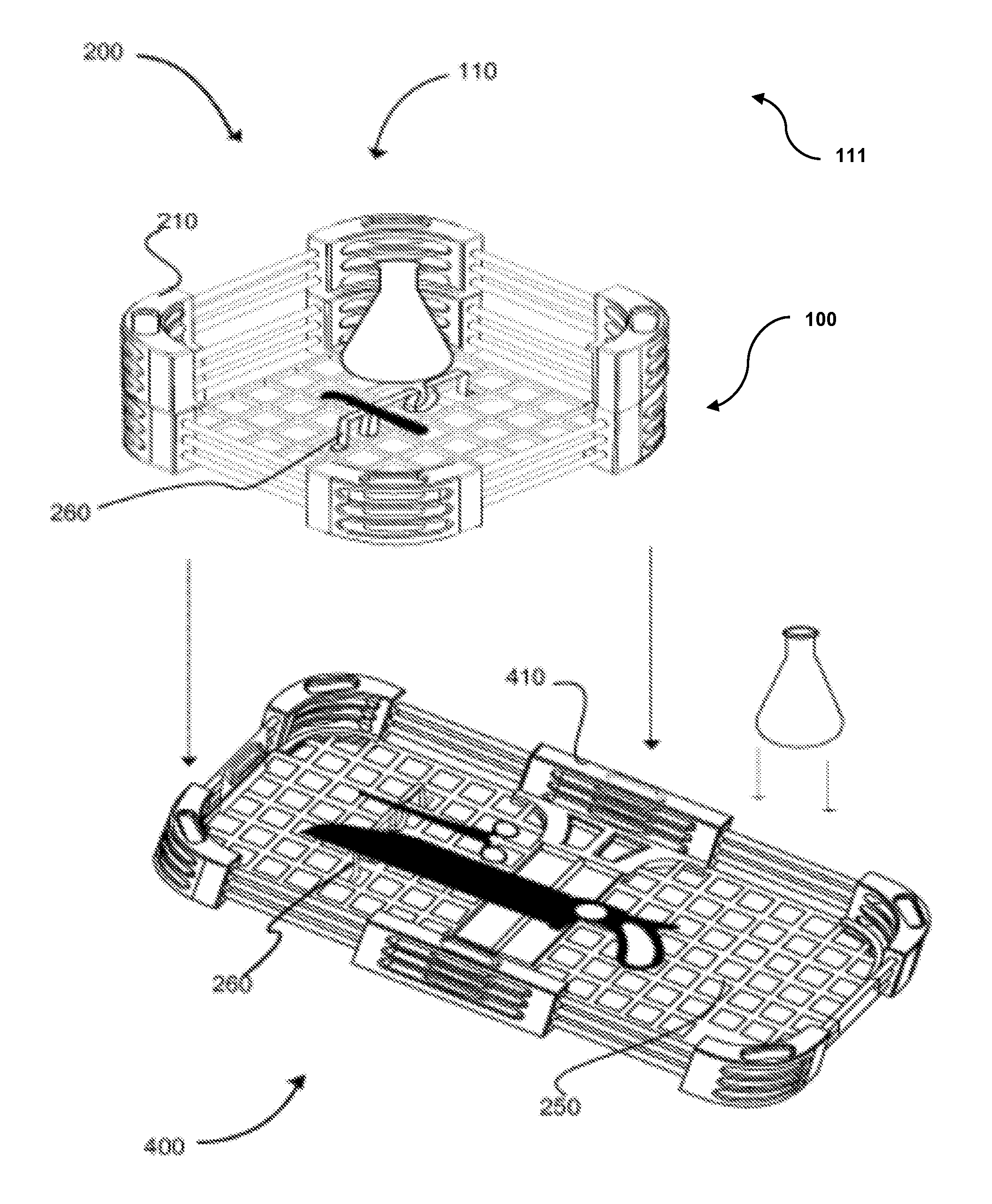
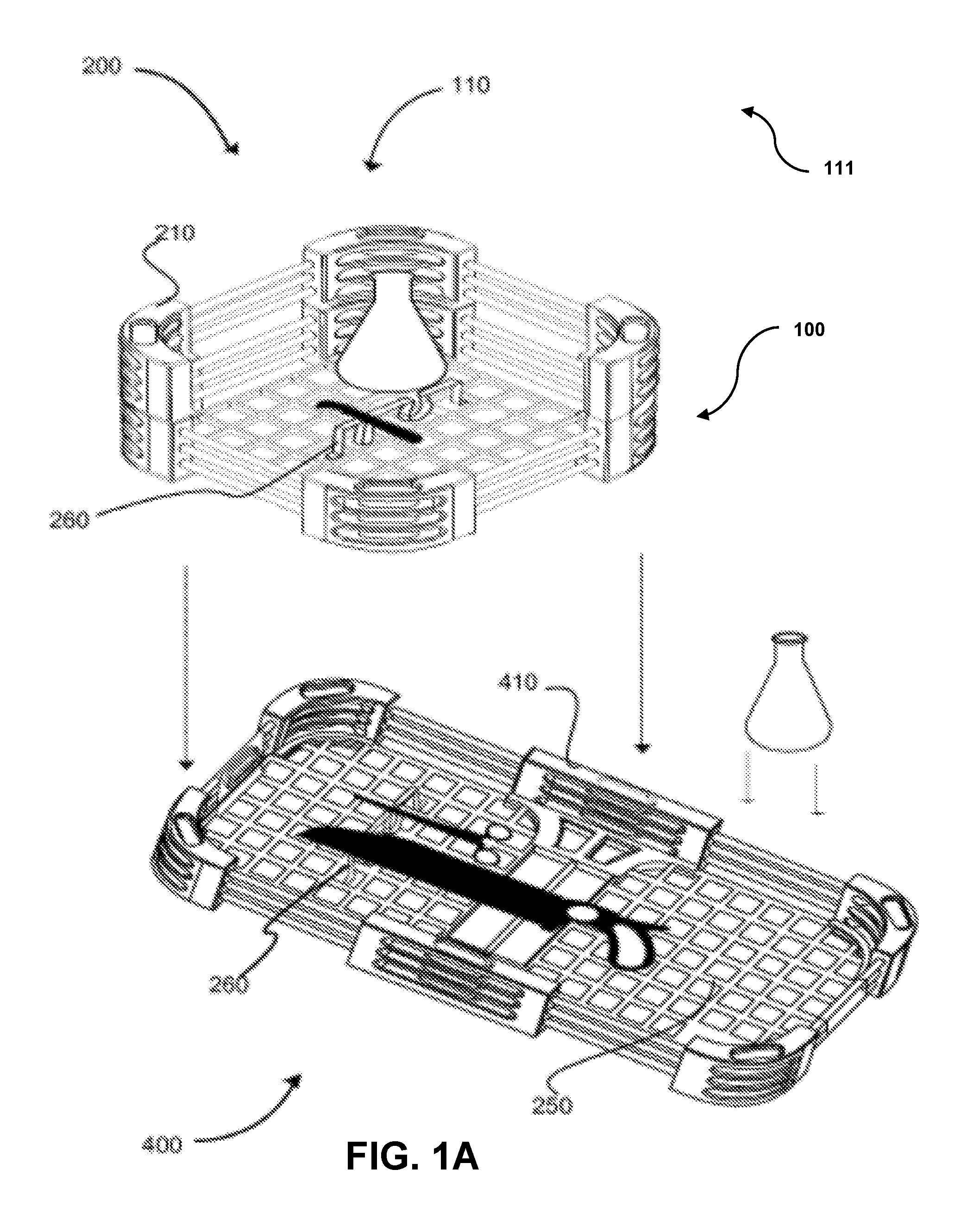
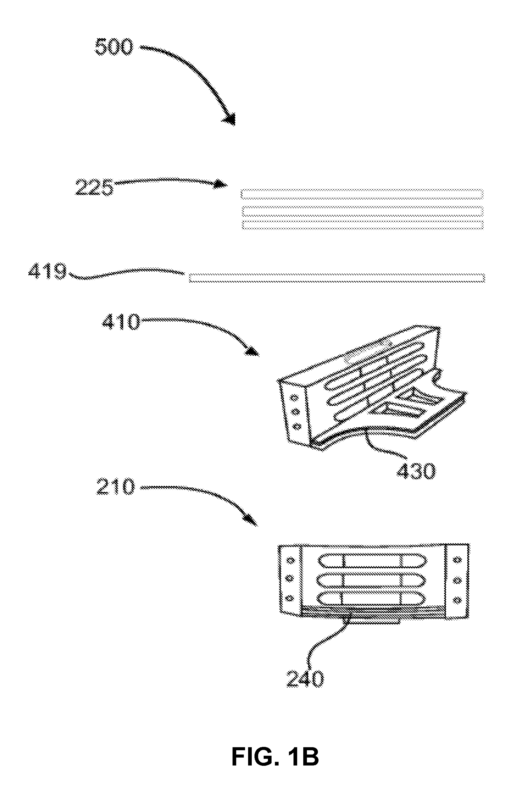
[0023]Referring now to FIG. 1A, showing a perspective view of modular sanitation tray system 100 of the present invention. Also shown is an exploded view of a corner receiver 210; three first dowel 225 (both illustrated in further detail in FIGS. 2A and 2B); side receiver 410; and second dowel 419 (both illustrated in further detail in FIGS. 4A and 4B). Examples of laboratory equipment frequently sanitized are shown within the tray. Modular sanitation tray system 100 comprises at least one first tray 200; optionally, at least one second tray 400, and optionally at least one rack 250. Modular sanitation tray system 100 may further comprise an optional instrument holder 260; and an optional handle 405 (shown and discussed in FIGS. 4 and 5). Finally, modular sanitation tray system 100 may optionally comprise a cover or lid (not shown) for added protection and increased sanitation capacity of modular sanitation tray system 100.

[0024]Within the present figure, modular sanitation tray sys...


PUM

PropertyMeasurementUnit
angleaaaaaaaaaa
shapeaaaaaaaaaa
shapesaaaaaaaaaa

Abstract

A sanitation tray system for medical, laboratory, and industrial equipment. This system is modular, stackable, and user customizable. It may be assembled in any number of horizontal or vertical configurations depending on the user's needs and is capable of permitting instruments of varying heights, lengths and widths to be sanitized simultaneously. It is easily assemblable and disassemblable and includes a rack, corners, sides, and dowels. It is lightweight, easy to manufacture, easy to ship, and economical. It is designed to use the least amount of surface area to allow for maximum permeation of sterilants and minimizes the opportunity for pooling of sterilants or retention of particulate matter while decreasing drying time.

Description

[0001]This application is a non-provisional of, and claims the benefit of the filing date of U.S. Provisional application No. 61 / 261,320 filed on Nov. 14, 2009.BACKGROUND OF THE INVENTION[0002]1. Field of the Invention[0003]The present invention relates generally to the field of sanitation and more specifically relates to sanitation trays.[0004]2. Description of the Related Art[0005]Trays are used to hold laboratory equipment and instruments as they are put through a sanitation / sterilization cycle in a machine such as a dishwasher or an autoclave. These types of trays are commonly used in hospitals, laboratories, and other industrial settings. A typical tray suited for this purpose usually comprises sides and a bottom and occasionally a lid and is generally designed to fit inside a sanitizing machine such as an autoclave or dishwasher. Equipment and instruments used in laboratory or hospital settings such as an operating room are commonly made of a sturdy material such as stainless ...

Claims


Application Information

Patent Timeline
Patent Type & Authority Patents(United States)
IPC IPC(8): A47B87/02B01L99/00A47B47/00B01L9/00
CPCA47B47/0091A47B87/0253B01L9/00A61B50/34B01L99/00A61B50/20A61B50/33B01L2200/028A61B2050/3007Y10T29/49826B01L13/02
Inventor ABENE, MICHAEL A.
Owner ABENE MICHAEL A
Why Eureka
Try Eureka