Microphone

a microphone and composite technology, applied in the direction of electrical transducers, transducer types, piezoelectric/electrostrictive transducers, etc., can solve the problems of increasing the size of the microphone in the diameter direction, increasing the weight of the microphone, and preventing the size of so as to eliminate the phase shift of the output signal, prevent the microphone from increasing in size, and improve the freedom of installation and handling

Inactive Publication Date: 2007-11-22
AUDIO-TECHNICA
View PDF3 Cites 12 Cited by
  • Summary
  • Abstract
  • Description
  • Claims
  • Application Information

AI Technical Summary

Problems solved by technology

When a player plays a musical instrument, however, there is a drawback that a stand supporting the microphone vibrates, the installation position of microphone will shift with this vibration and the initial installation position can not be maintained, resulting in a phase difference in the output signals of the mutual microphones.
However, since the conventional composite type microphone is made by disposing two microphone units in parallel to integrate, a drawback is that the microphone is increased in size in the diameter direction.
Since the upsized microphone is difficult to install and increases its weight, a drawback is that the microphone stand also needs to have a robust structure, thus increasing its weight and causing a difficulty in handling.

Method used


Image

  • Microphone
  • Microphone
  • Microphone

Examples


Embodiment Construction

[0020]An embodiment of a microphone concerning the present invention will be described hereinafter with reference to the accompanying drawing.

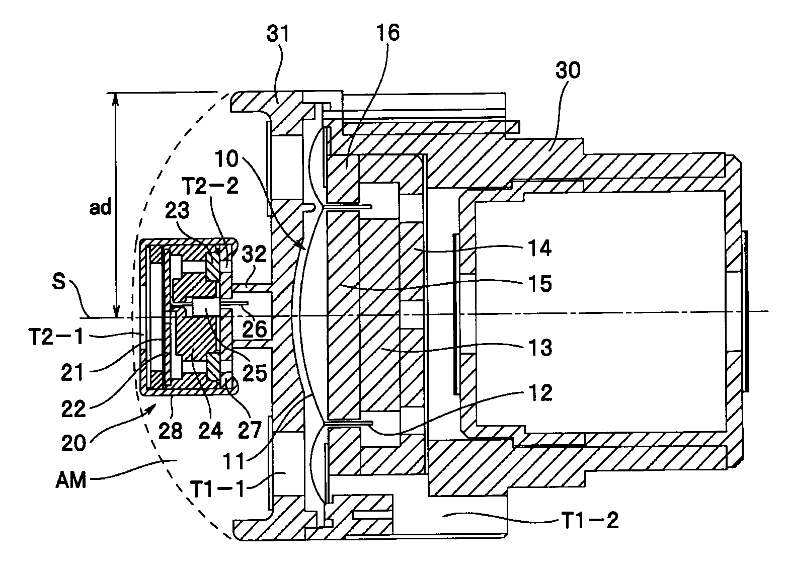
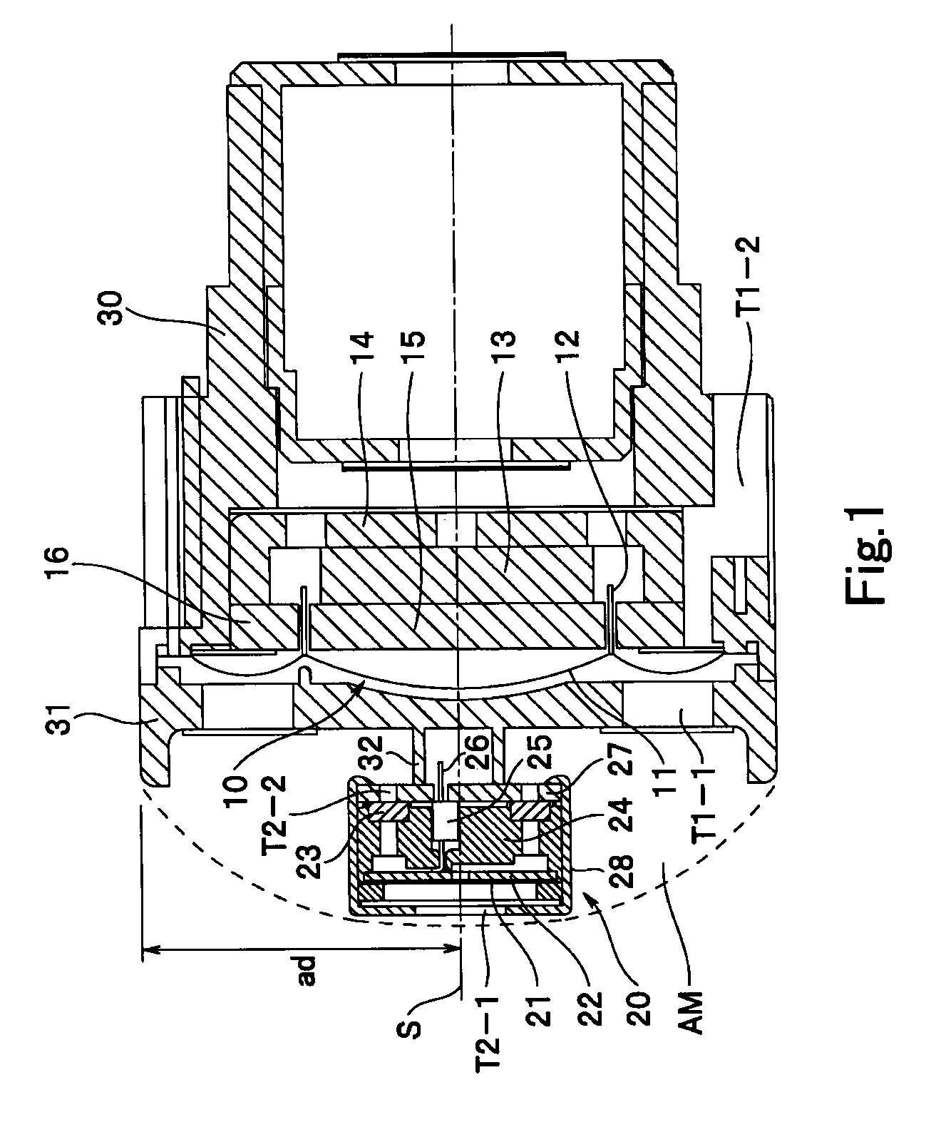
[0021]In FIG. 1, in a front end portion (at the left end portion in FIG. 1) of a case 30 serving as a microphone body that is formed in a cylindrical shape, a dynamic microphone unit 10 is incorporated as a first microphone unit. Also to the microphone body case 30, a condenser microphone unit 20 projecting forwardly from the front end of the microphone body case 30 is attached as a second microphone unit. Accordingly, two microphone units of different electroacoustic conversion methods are incorporated in the common microphone body case 30 to constitute a composite type microphone.

[0022]The dynamic microphone unit 10 includes a diaphragm 11 as a vibrating plate disposed at the front end portion of the microphone body case 30, a coil 12 projectingly secured to the back face side of the diaphragm 11, a permanent magnet 13, a back yoke 14, a fro...


PUM


Abstract

To obtain a composite type microphone, the microphone preventing an increase in size and weight and thereby improving the freedom for installation and handling while keeping the phases of signals output from respective microphone units the same. A composite type microphone that incorporates microphone units of different electroacoustic conversion methods into a common microphone body is provided. Here, in a front acoustic terminal portion of a first microphone unit based on one electroacoustic conversion method, a second microphone unit based on another electroacoustic conversion method is disposed, and in the front acoustic terminal portion of the first microphone unit, an air that vibrates in the same phase with that of a vibrating plate of the first microphone unit exists, and within the air that vibrates in the same phase with that of the vibrating plate of the first microphone unit, the second microphone unit is disposed.

Description

BACKGROUND OF THE INVENTION[0001]1. Field of the Invention[0002]The present invention relates to a composite type microphone that incorporates a plurality of microphone units of different electroacoustic conversion methods into a common microphone body, e.g., the composite type microphone capable of disposing a condenser microphone unit in a front acoustic terminal portion of a dynamic microphone unit.[0003]2. Related Background of the Invention[0004]In recording a sound generated from the same musical instrument or the like, microphones of different electroacoustic conversion methods, e.g., a dynamic microphone and a condenser microphone, are sometimes disposed side by side for use. This is intended to record a sound from the same sound source with a plurality of microphones of different conversion methods and mix the output signals of the respective microphones, thereby taking advantage of the characteristics of the respective microphones, because the microphones of different elec...

Claims


Application Information

Patent Timeline
Patent Type & Authority Applications(United States)
IPC IPC(8): H04R25/00H04R19/04H04R11/04H04R17/02
CPCH04R1/245H04R23/02H04R19/04H04R9/08
Inventor AKINO, HIROSHINEMOTO, MITSUO
Owner AUDIO-TECHNICA
Why Eureka
Try Eureka