Cordless window blind structure

Inactive Publication Date: 2007-11-29
CHING FENG BLINDS INC CO LTD
View PDF7 Cites 38 Cited by
  • Summary
  • Abstract
  • Description
  • Claims
  • Application Information

AI Technical Summary

Benefits of technology

[0003]It is, therefore, the primary purpose of the present invention to provide a cordless window blind structure wherein an operational cord attached to a cord-winding control device is correspondingly linked in movement to lift cords wound onto a movable seat and a fixed seat so that a bottom rail is simply pushed or pulled by hands to freely adjust the height of a blind body in an easy manner without the hands abraded by the conventional pull cords, achieving the best state of application thereby.
[0004]It is, therefore, the second purpose of the present invention to provide a cordless window blind structure wherein the cord-winding control device is equipped with torsion springs whose elasticity permit the operational cord to precisely recoil and locate in place according to the pushing/pulling force applied by the hands onto the b

Problems solved by technology

Due to the small frictional surface thereof, the pull cords tend to rub against the hands or even abrade the hands directly contacting with them in an uncomfortable way if the pull cords are drawn to slide too fast.
Thus, great efforts must be spent to draw the pull cords in operation, and the pull cords can easily get stuck in the pulley assembly, resulting in an aw

Method used


Image

  • Cordless window blind structure
  • Cordless window blind structure
  • Cordless window blind structure

Examples


Embodiment Construction

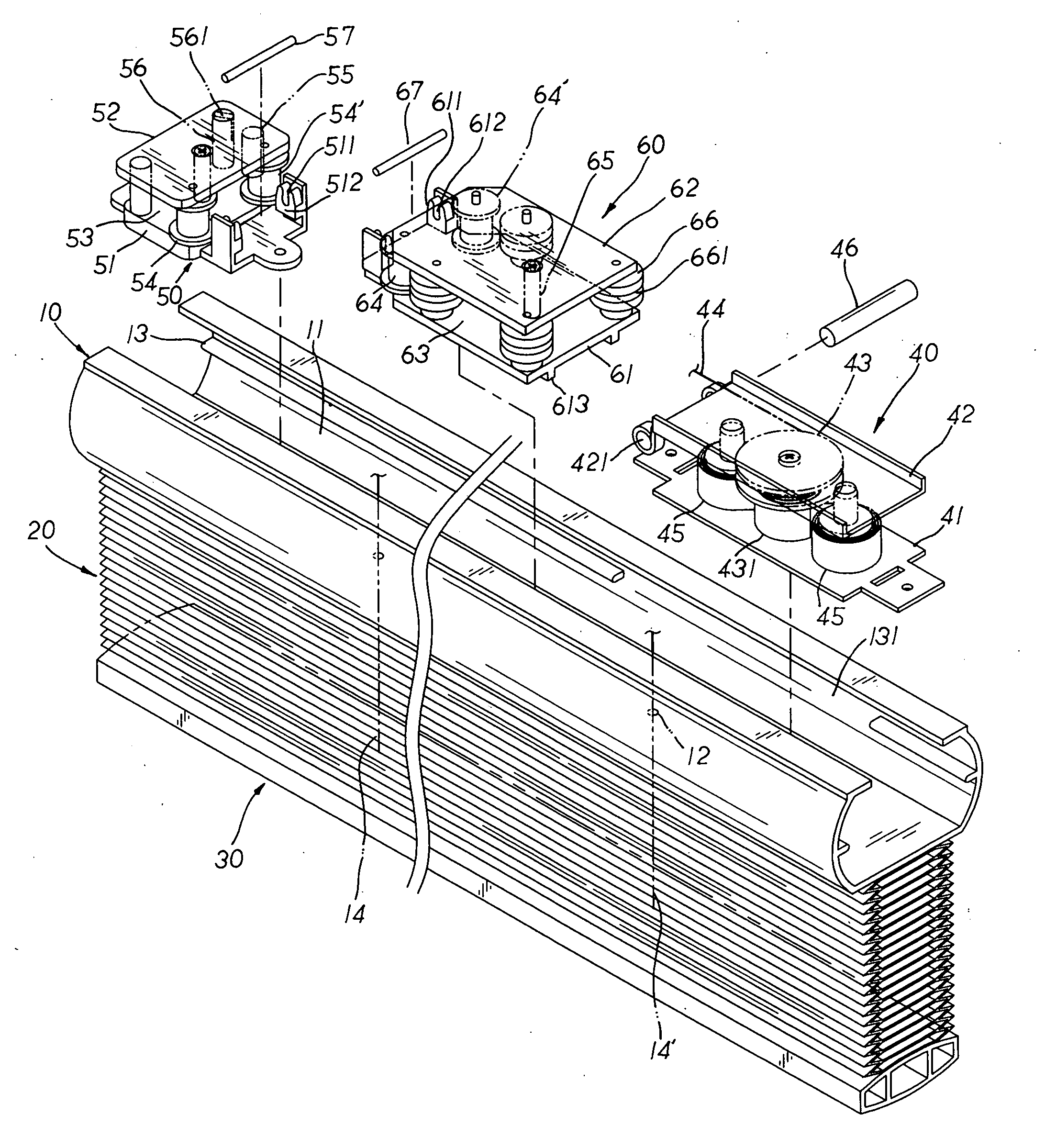
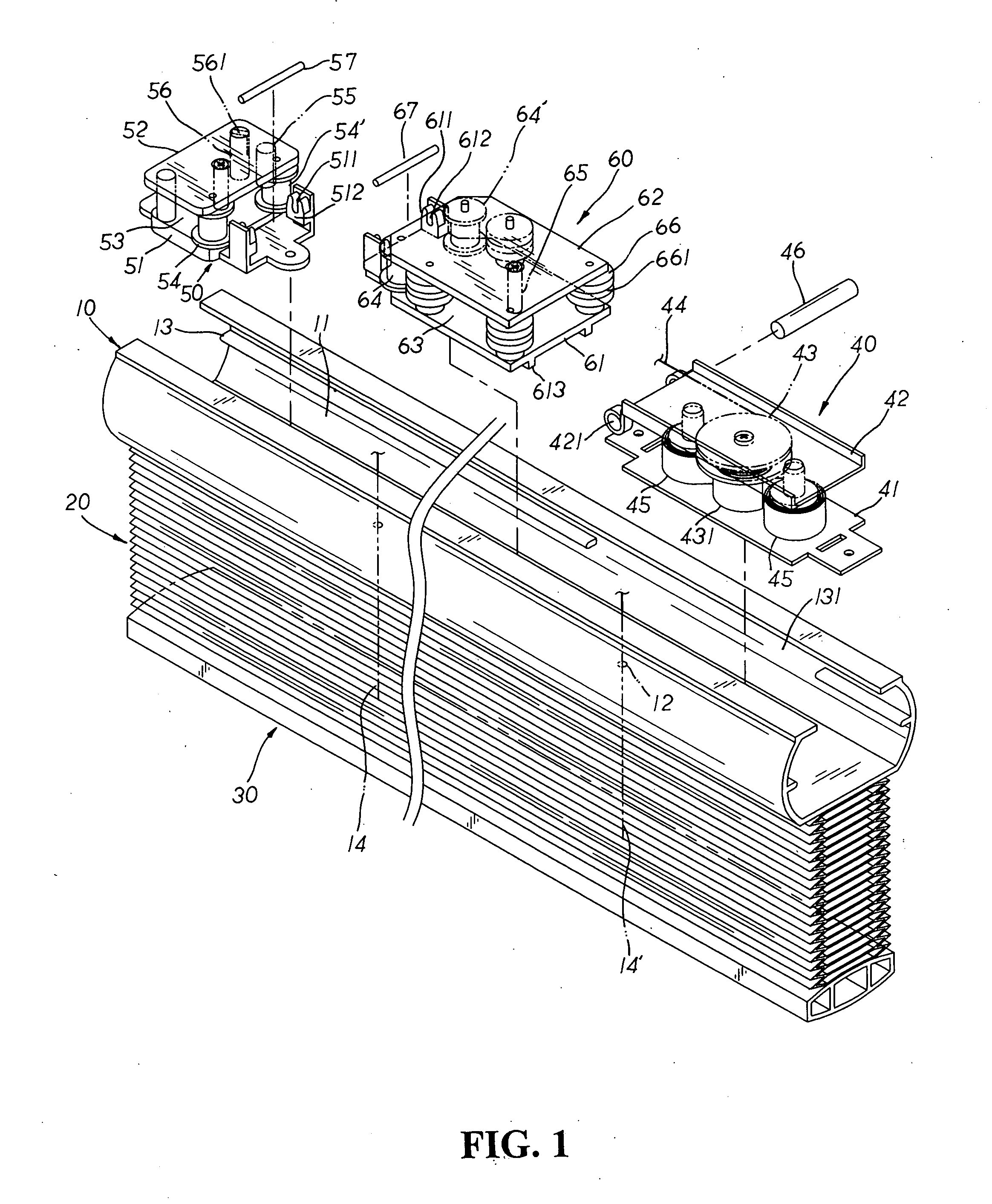
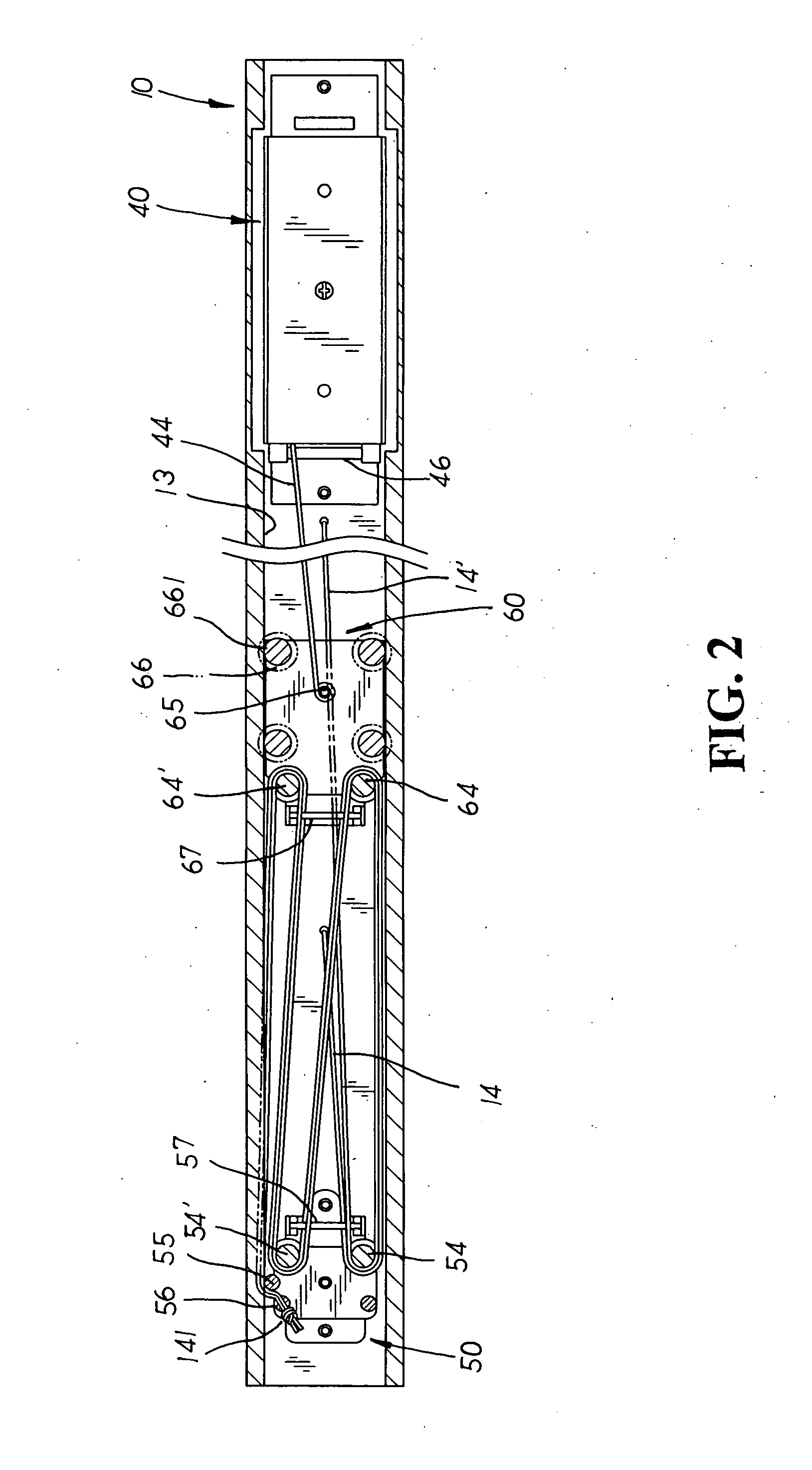
[0011]Please refer to FIG. 1 showing an exploded perspective view of the present invention. The present invention relates to a cordless window blind structure, comprising a head rail 10, a blind body 20, a bottom rail 30, a cord-winding control device 40, a fixed seat 50, and a movable seat 60. The upper side of the head rail 10 is defined by an accommodating channel 11 with cord passages 12 disposed thereon, and both internal side walls of the accommodating channel 11 are disposed a pair of symmetrically-extending guide tracks 13 each having a positioning recess 131 cut thereon. The blind body 20 is fixed between the head rail 10 and the bottom rails 30 thereof, and two or more than two lift cords 14, 14′ are mounted to the corresponding locations of the blind body 20 and the bottom rail 30 thereon. One end of each lift cord 14, 14′ is guided to pass through the cord passage 12 of the head rail 10 while the other end thereof is fixed to the bottom rail 30 thereon. The cord-winding ...


PUM


Abstract

A cordless window blind structure comprises a head rail having an accommodating channel into which a cord-winding control device with an operational cord attached thereto and a fixed seat are mounted at both end sides with a movable seat situated there-between. The operational cord is also fixed to one side of the movable seat. Multiple lift cords mounted to the corresponding positions of a blind body and a bottom rail are guided into the accommodating channel and divided to extend from either the upper or lower side of a guiding post of the fixed and movable seats respectively and wind onto multiple guiding elements, permitting the operational cord to link in movement to the lift cords wound onto the movable and fixed seats. Therefore, the bottom rail is simply pushed or pulled by hands to easily and accurately adjust the blind body into a desirable collected or expanded position thereby.

Description

BACKGROUND OF THE INVENTION[0001]The present invention relates to a cordless window blind structure, comprising a head rail having an accommodating channel into which a cord-winding control device with an operational cord attached thereto and a fixed seat are mounted at both ends with a movable seat situated there-between wherein the operational cord is correspondingly linked in movement to lifts cords so that a bottom rail is simply pushed or pulled by hands to loosen or tighten the lift cords wound on the movable seat and synchronically actuate the operational cord therewith, facilitating easier and simpler adjustment of a blind body into a desirable collected or expanded position.[0002]Conventional window blinds usually have pull cords mounted to suspend at one side of a blind body and retained in position by a pulley assembly to collect or expand the blind body thereby. In operation, the pull cords are drawn by force of hands to adjust the position of the blind body. Due to the ...

Claims


Application Information

Patent Timeline
IPC IPC(8): A47H5/00
CPCE06B2009/3222E06B9/322
Inventor LIANG, WEN YING
Owner CHING FENG BLINDS INC CO LTD
Why Eureka
Try Eureka