Headrail covering structure for blinds

a blind and covering technology, applied in the direction of door/window protective devices, building components, constructions, etc., can solve the problems of reducing the durability of the blind, affecting the service life of the blind, and the assembling parts of the headrail to get jammed, so as to improve the service life and reduce the cost of production. , the effect of boosting economic benefits and competitiveness

Inactive Publication Date: 2008-11-27
CHING FENG BLINDS INC CO LTD
View PDF4 Cites 25 Cited by
  • Summary
  • Abstract
  • Description
  • Claims
  • Application Information

AI Technical Summary

Benefits of technology

[0003]It is, therefore, the primary purpose of the present invention to provide a headrail covering structure for blinds wherein connecting elements each having a set of upper and lower conjoining surfaces are utilized and combined with a covering sheet so as to shelter a receiving channel of a headrail and protect each assembling part mounted to the receiving channel therein, achieving dustproof effect; whereby, the window blind can be easily and smoothly operated without a lift cord mounted inside the headrail getting caught or jammed by dust or dirt as found in the above conventional blind structure, achieving the best application state thereby.
[0004]It is, therefore, the second purpose of the present invention to provide a headrail covering structure for blinds wherein the connecting element is equipped with a certain thickness and composed of a set of upper and lower conjoining surfaces, permitting speedy and easy assembly of the covering sheet so as to reduce the cost of production, and boost economical benefit and the competitiveness of the present invention thereby.

Problems solved by technology

In the long run, dust and dirt can easily collect in the headrail and become hard to clean, which can cause the assembling parts accommodated inside the headrail to get jammed and unable to move in operation.
Thus, in case the headrail has too much dust or dirt accumulated therein, the assembling parts received therein will fail to actuate the movement of the lift cords smoothly, which can not only cause the inconvenience in application but also reduce their durability thereof.

Method used


Image

  • Headrail covering structure for blinds
  • Headrail covering structure for blinds
  • Headrail covering structure for blinds

Examples


Embodiment Construction

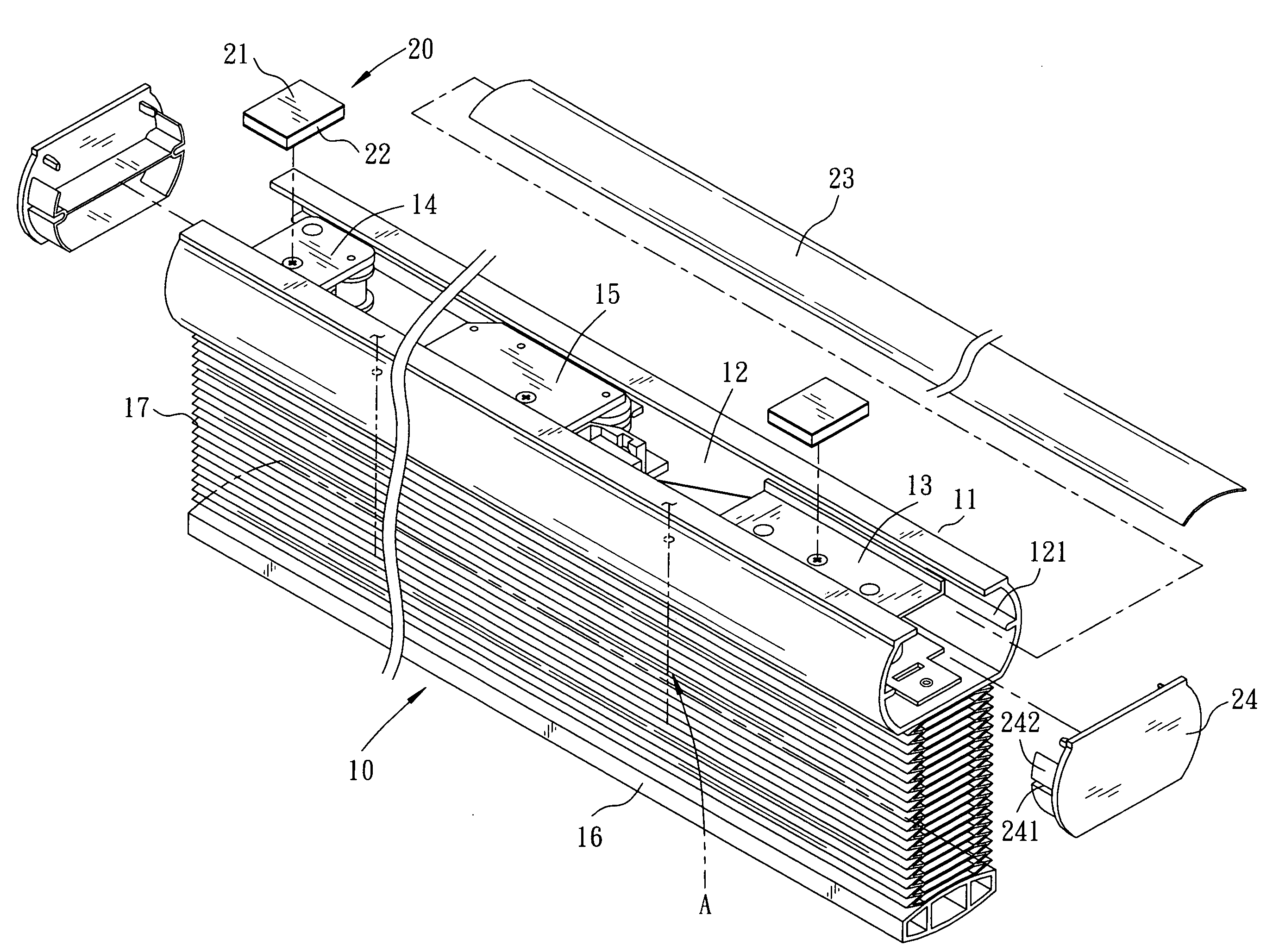
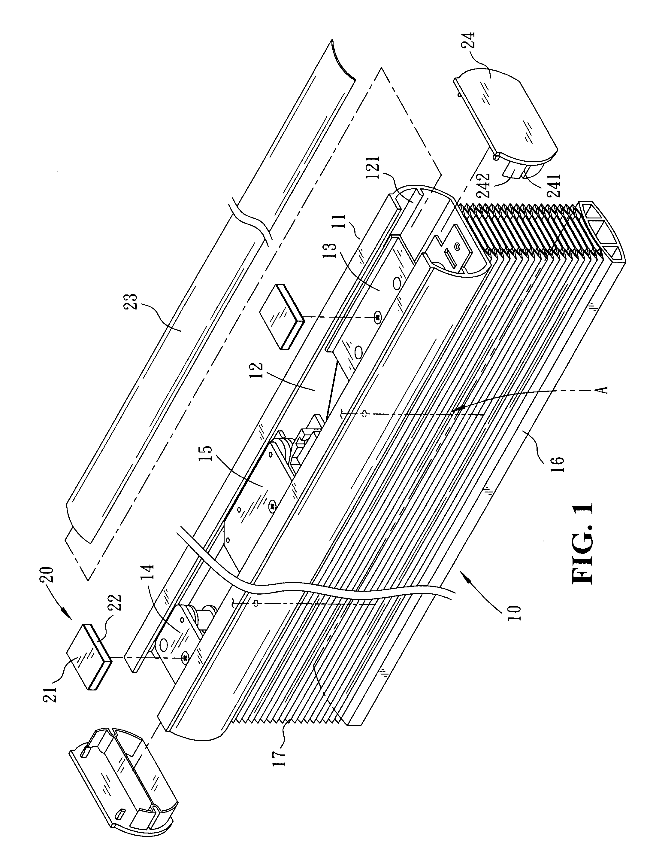
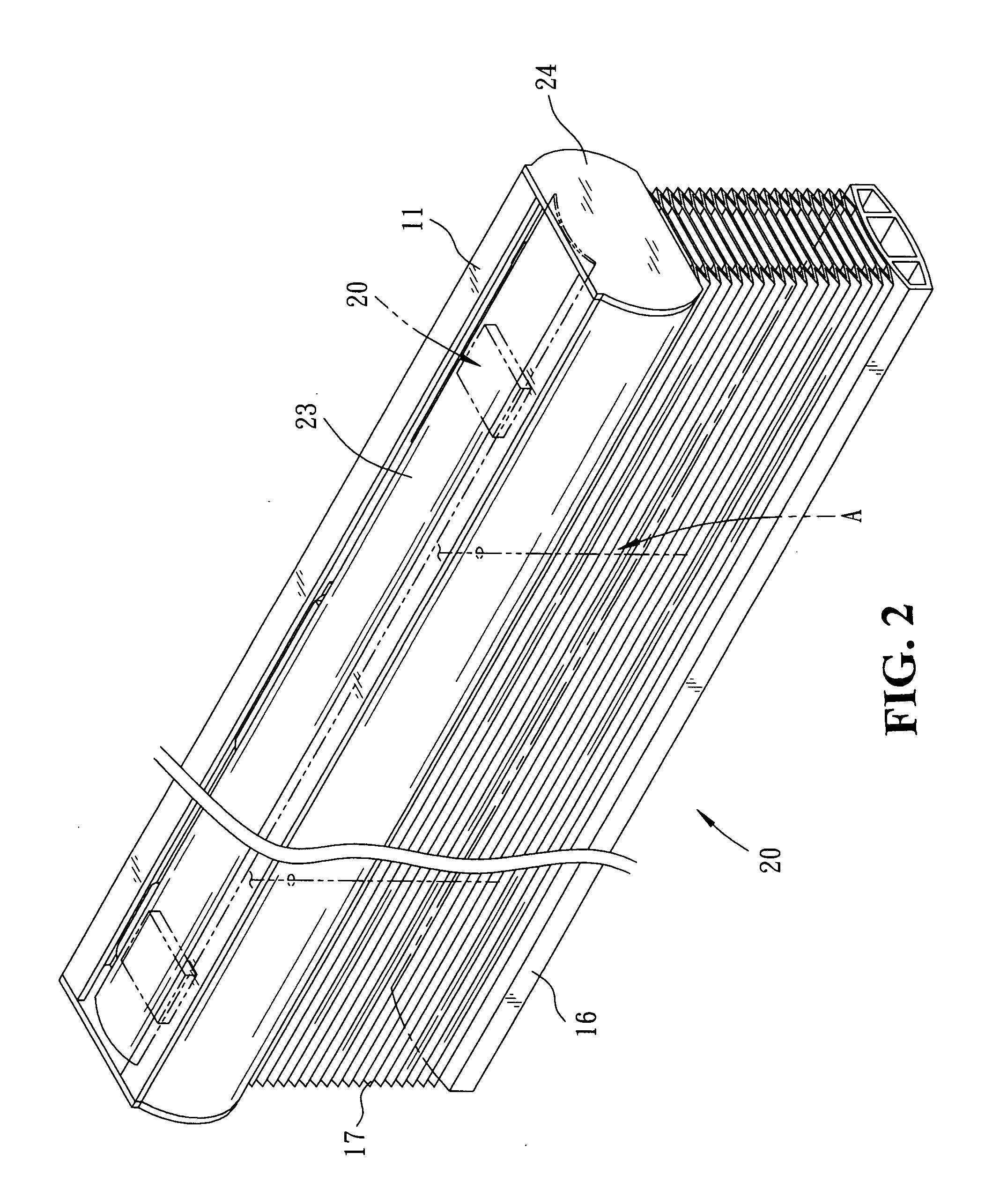
[0009]Please refer to FIG. 1 showing an exploded perspective view of the present invention (accompanied by FIGS. 2 to 4 inclusive). The present invention relates to a headrail covering structure for blinds, comprising a headrail 11 having a top side defined by a receiving channel 12, and a cord-winding control device 13 and a fixed seat 14 are respectively mounted and fixed to both end sides of the receiving channel 12 therein. A movable seat 15 is accommodated between the cord-winding control device 13 and the fixed seat 14 to slide along the inner sidewalls of the receiving channel 12 thereon. A lift cord A mounted to a bottom rail 16 and a blind body 17 is wound through the movable seat 15 and the fixed seat 14 to be coiled or released by the cord-winding control device 13 so as to actuate the movable seat 15 and, thus, collect upwards or expand downwards the blind body 17 therewith, providing a cordless window blind 10 thereby. The cord-winding control device 13 and the fixed se...


PUM


Abstract

A headrail covering structure for blinds comprises a headrail defined by a receiving channel to which a cord-winding control device, a movable seat, and a fixed seat are respectively mounted so as to control a lift cord and actuate a blind body collected upwards or expanded downwards thereby, forming a cordless window blind structure. The cord-winding control device and the fixed seat have the top surfaces respectively equipped with a connecting element composed of a set of upper and lower conjoining surfaces. A covering sheet identical to the headrail in length is provided to attach to the upper conjoining surfaces of the connecting elements, while the lower conjoining surfaces of the connecting elements are respectively adhered onto the cord-winding control device and the fixed seat. Therefore, via the sheltering of the covering sheet, the receiving channel of the headrail can achieve dustproof effect and protect each assembling part accommodated therein.

Description

BACKGROUND OF THE INVENTION[0001]The present invention relates to a headrail covering structure for blinds, comprising a headrail having a cord-winding control device, a movable seat, and a fixed seat mounted thereto wherein connecting elements each having a set of upper and lower conjoining surfaces are adhered onto the top surfaces of the cord-winding control device and the fixed seat respectively, and a covering sheet identical to the headrail in length is attached to the upper conjoining surfaces of the connecting elements; whereby, via the sheltering of the covering sheet, the headrail can achieve dustproof effect and protect each assembling part accommodated therein.[0002]Conventional window blinds include headrails with hollow-out top sides exposed outwards. In the long run, dust and dirt can easily collect in the headrail and become hard to clean, which can cause the assembling parts accommodated inside the headrail to get jammed and unable to move in operation. Furthermore,...

Claims


Application Information

Patent Timeline
Patent Type & Authority Applications(United States)
IPC IPC(8): E06B9/323
CPCE06B9/323
Inventor YING, LIANG WEN
Owner CHING FENG BLINDS INC CO LTD
Why Eureka
Try Eureka