Roller chain automatic transmission

a technology of automatic transmission and roller chain, which is applied in the direction of gearing, gearing elements, hoisting equipment, etc., can solve the problems of affecting the efficiency of manual transmission, the transmission is heavy and getting heavier and less efficient, and the geared automatic transmission technology has changed little in 50 years

Inactive Publication Date: 2007-04-19
LEW HLDG
View PDF2 Cites 6 Cited by
  • Summary
  • Abstract
  • Description
  • Claims
  • Application Information

AI Technical Summary

Benefits of technology

[0004] The present invention breaks this impasse in automatic transmissions by exceeding the best manual transmission today in efficiency. It can approach this efficiency using a single set of varying diameter roller chain sprockets because it is in effect a single set of roller chain sprockets which are known to average 98.5% efficiency in normal use. A roller chain is efficient because it is essentially a wheel and axle means to transfer rotational loads to different RPMs.

Problems solved by technology

In vehicle transmissions in particular, we have been plagued with geared automatic transmission technology that has changed little in 50 years.
Such transmissions are heavy and getting heavier and less efficient by adding more ratios or getting less rugged and less efficient than manual transmissions by use of steel belts and pulleys in CVTs (continuously variable transmissions).
Efficiency is so poor, present automatic transmissions require oil coolers to stay operational.
But, CVTs use “friction force” to transfer torque and have limited ratio capability, about 6:1.
This is a big disadvantage for two main reasons; CVTs can be easily “smoked” (ruined) by slippage when heavily loaded, and developing belts for different transmission sizes is a monumental task.

Method used


Image

  • Roller chain automatic transmission
  • Roller chain automatic transmission

Examples


Embodiment Construction

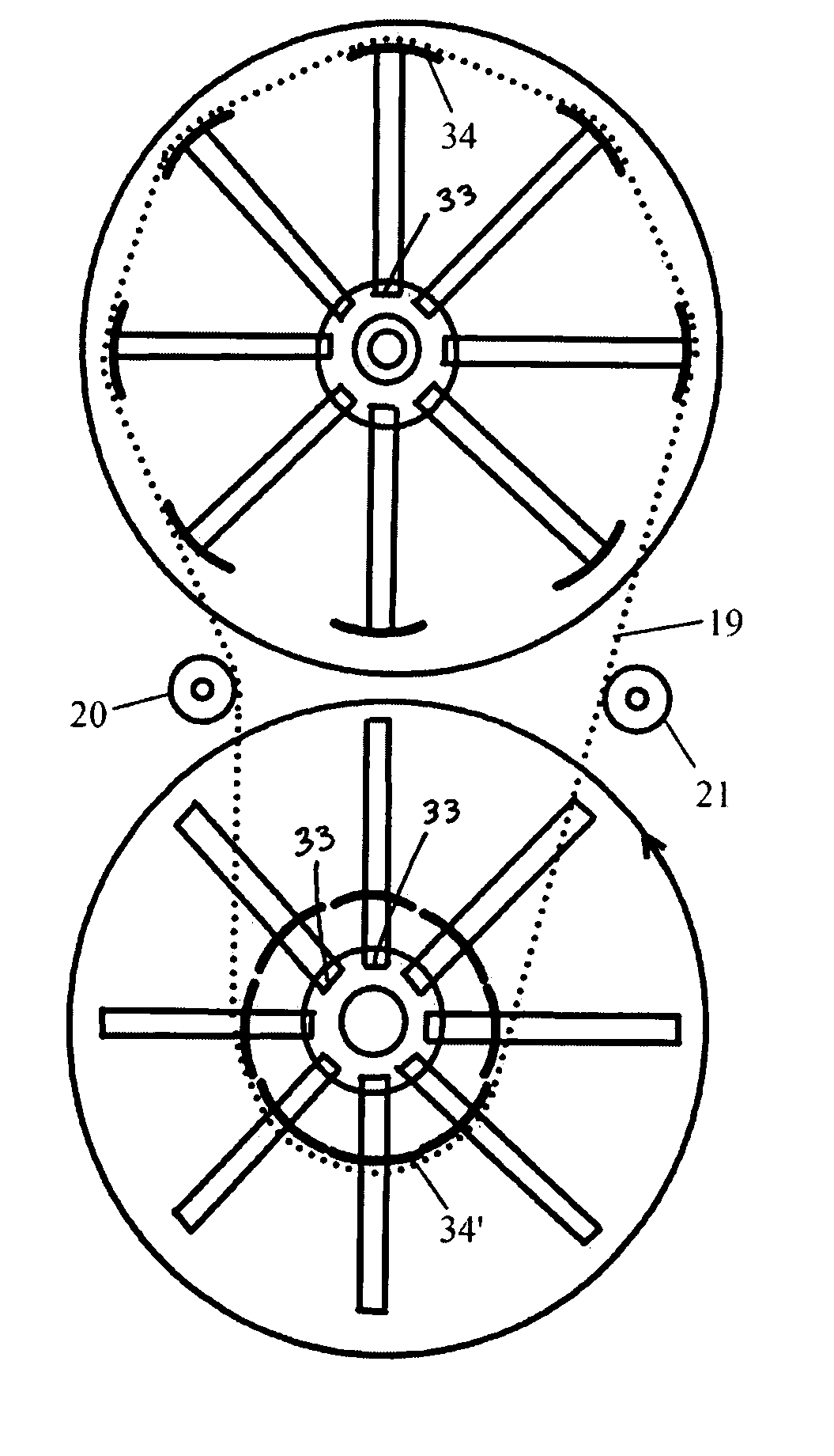
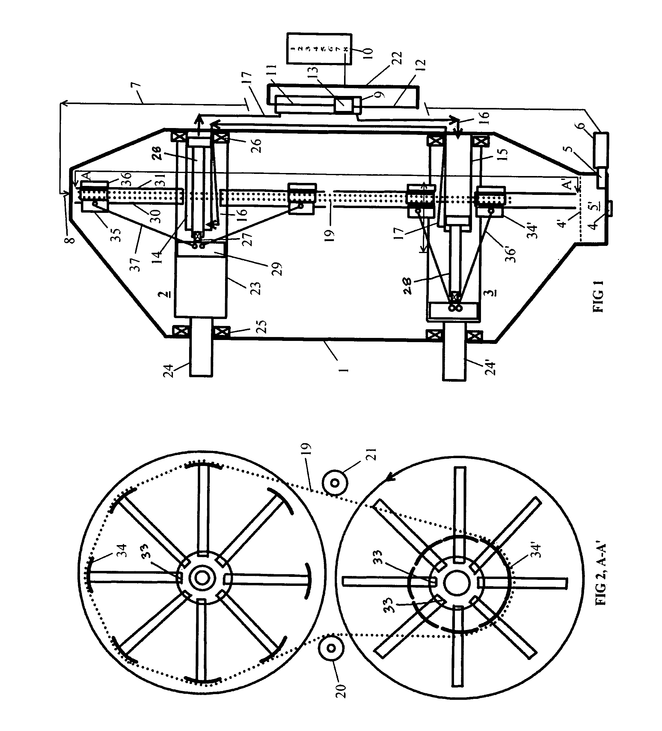
[0012] Starting with FIG. 1, a roller chain transmission in accordance with one embodiment has an outer housing 1 housing a segmented variable diameter top sprocket assembly 2 and similar lower sprocket assembly 3. The roller chain transmission further includes a recirculating lubrication system comprising a drain plug 4, lubricating oil 4′, and a circulating pump 5 with filter 6. Lubricating oil 4′ is circulated through lines 7 and empties onto the top sprocket assembly 2 at an inlet 8 wherein oil 4′ and trickles back down to sump 5′.

[0013] Shifting master cylinder 9 is shown with shifting positions 10 and has rods 11 and 12 on either end of piston 13 to cause hydraulic fluid such as oil to shift into and out of sprocket shifting sprocket cylinders 14 and 15 respectively. As can be seen, movement of the piston 13 in master cylinder 9 causes oil flows 16 and 17 into and out of cylinders 14 and 15, respectively, causing one cylinder to contract and one to extend simultaneously. Thus...


PUM


Abstract

An automatic transmission comprised of toothed sprocket segments to form varying dual sprocket diameters with parallel shafts to achieve a wide range of ratios using scissor-type linkages to vary the sprocket diameters actuated by coordinated hydraulic cylinders in each sprocket assembly which are in turn actuated by a single double acting master cylinder to coordinate final sprocket diameters such that a constant length chain can be used at any selected ratio position on the master cylinder.

Description

CROSS REFERENCES TO RELATED APPLICATIONS [0001] This application claims the benefit of U.S. Provisional Application Ser. No. 60 / 726,274, filed Oct. 13, 2005.BACKGROUND OF THE INVENTION [0002] The current energy crisis demands more efficient automatic transmission solutions for vehicles that are flexible, low cost and long lived. In vehicle transmissions in particular, we have been plagued with geared automatic transmission technology that has changed little in 50 years. Such transmissions are heavy and getting heavier and less efficient by adding more ratios or getting less rugged and less efficient than manual transmissions by use of steel belts and pulleys in CVTs (continuously variable transmissions). Efficiency is so poor, present automatic transmissions require oil coolers to stay operational. Indeed, such transmissions do well to average 80-85 percent efficiency (lowest heavily loaded). Manual automobile transmissions average about 90% efficiency. [0003] One proposed transmiss...

Claims


Application Information

Patent Timeline
Patent Type & Authority Applications(United States)
IPC IPC(8): F16H55/54F16H63/00
CPCF16H9/10F16H55/54
Inventor WEAVER, LLOYD E.
Owner LEW HLDG
Why Eureka
Try Eureka