

Material cutting and conveying device
A technology for conveying devices and materials, applied in metal processing and other directions, can solve the problems of sticking together, inconvenient transportation and packaging, etc., and achieve the effect of improving practical life, simple and smooth operation process, and convenient operation.
- Summary
- Abstract
- Description
- Claims
- Application Information
AI Technical Summary
Problems solved by technology
Method used
Image


Examples
Embodiment 1
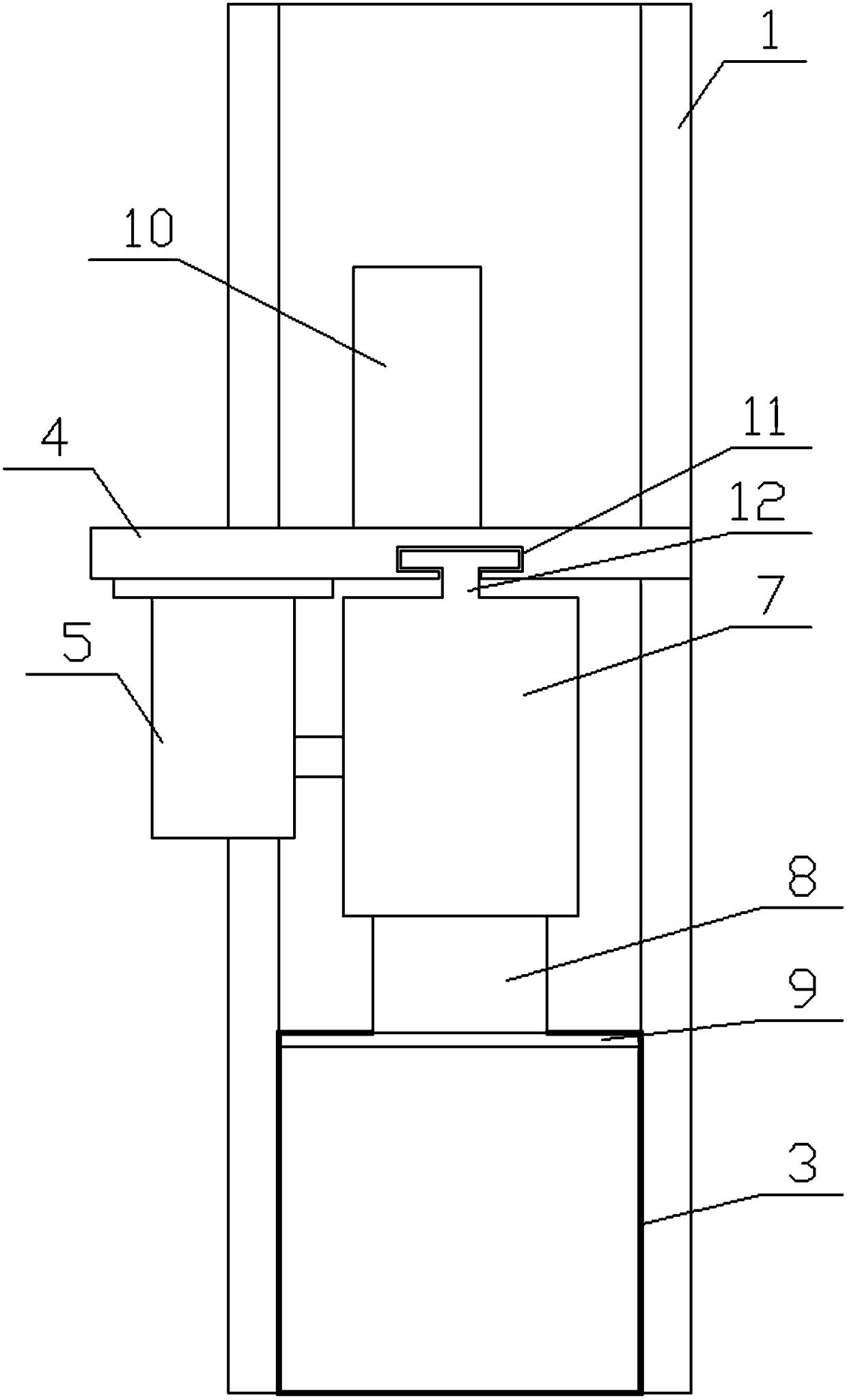
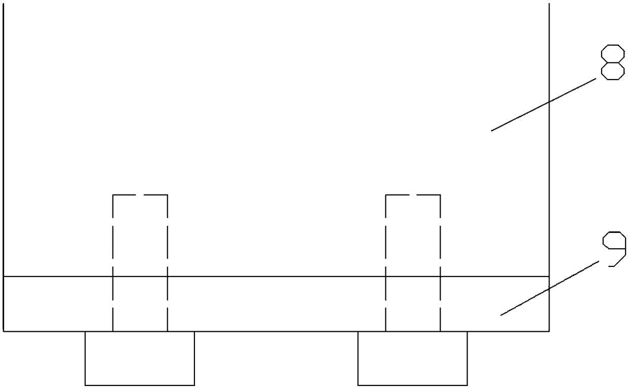
[0028] Embodiment 1. First, put the semi-finished material into the vertical hollow feed pipe 1 until the bottom of the semi-finished material is placed on the conveyor belt 2, turn on the rotating motor 5, and the rotating motor 5 drives the incomplete gear 6 to rotate. The complete gear 6 first contacts with the gear bar 13 on the bottom of the loop 7, and the convex slide block 12 on the loop 7 slides left and right in the convex chute 11 to ensure the accuracy of the loop 7 running track. Correctness, so at the beginning, the return-shaped collar 7 is driven inward by the incomplete gear 6, and the cutting knife 9 is pushed through the L-shaped connecting rod 8 to extend from the upper edge of the discharge port 3 to the vertical hollow feed pipe 1 The semi-finished material is cut off inside, and then the conveyor belt 2 transports the material away. At this time, the incomplete gear 6 continues to rotate to the position in contact with the gear bar 13 on the upper side of...
Embodiment 2
[0029] Embodiment 2. This device is a part of the entire material processing production line. The vertical hollow feed pipe 1 is fixedly connected to other positions of the production line, and the right end of the horizontal installation plate 4 is fixedly connected to the vertical hollow feed pipe 1, and the horizontal installation plate 4 and the vertical hollow feed pipe 1 are provided with a diagonal tie rod 10, which plays the role of reinforcement and stability. The material cutting part and the motor drive part are installed on the horizontal mounting plate 4, and the horizontal mounting plate 4 The convex chute 11 provided on the top not only plays the role of load-bearing loop 7, L-shaped connecting rod 8 and cutting knife 9, but also plays the role of controlling the running track of the loop 7, and by adjusting the rotating motor 5 The rotating speed can determine the speed of the whole material cutting and conveying.
[0030] Based on the above, the present invent...
PUM
 Abstract
Description
Claims
Application Information