
Cold upsetting die and machining technology thereof

A processing technology and mold technology, applied in the field of cold heading die and its processing technology, can solve the problems affecting the product quality of cold heading forming, affecting the assembly accuracy and service life between the mold core and the mold sleeve, and the damage of the mold sleeve, etc.

Inactive Publication Date: 2017-07-18
SANMEN TONGSHUN RIVET
View PDF10 Cites 16 Cited by
  • Summary
  • Abstract
  • Description
  • Claims
  • Application Information

AI Technical Summary

Problems solved by technology

The core of this kind of cold heading mold is installed in the core through interference fit. The deviation, on the one hand, will affect the quality of cold heading products, and on the other hand, it will affect the service life of the mold core and mold sleeve
In addition, since the mold core is a vulnerable part, when the mold core is greatly worn, it is necessary to use a large thrust to withdraw the mold core from the mold sleeve and then replace the mold core again
Due to the interference fit between the mold core and the mold sleeve, it is easy to cause damage to the mold sleeve during the replacement process, which affects the assembly accuracy and actual service life between the mold core and the mold sleeve

Method used


Image

  • Cold upsetting die and machining technology thereof
  • Cold upsetting die and machining technology thereof
  • Cold upsetting die and machining technology thereof

Examples


Embodiment 1

[0058] Embodiment one, a kind of cold heading mold,

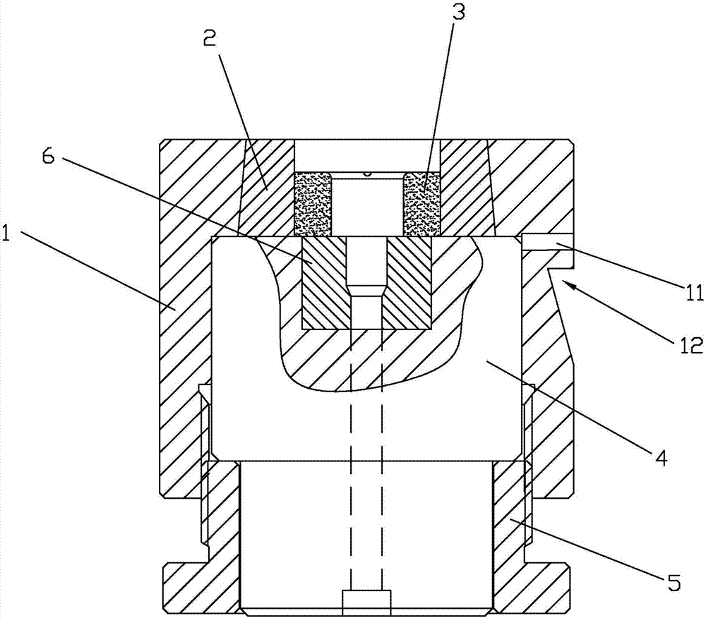
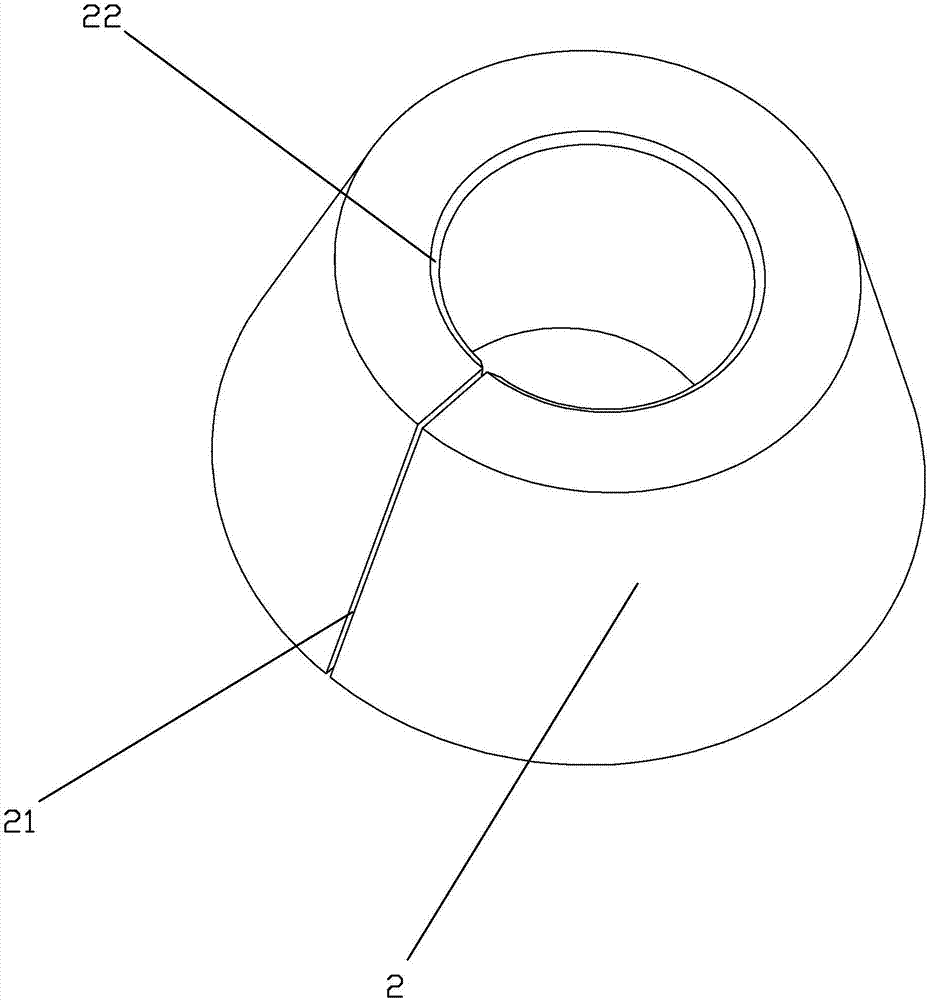
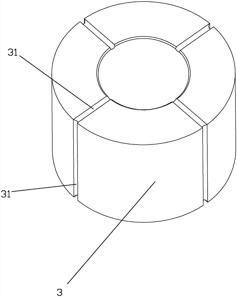
[0059] Such as Figure 1 to Figure 3 As shown, a cold heading die includes a cylindrical formwork 1, the outer surface of the formwork 1 is provided with a positioning groove 12, the positioning groove 12 is cut by wire cutting, and the positioning groove 12 includes a shaft with the formwork 1 To a vertical face and an inclined plane, the angle between the inclined plane and the axis of the formwork 1 is 15°. The setting of the positioning groove 12 can cooperate with the fiber parts on the cold heading machine to prevent the mold from rotating after being loaded into the cold heading machine. There is an axial stepped hole in the formwork 1, the stepped hole runs through the upper and lower end surfaces of the formwork 1, the small end of the stepped hole is a tapered section, and communicates with the upper end surface of the formwork 1, the axial section of the tapered section is conical ; The big end of the stepped h...

Embodiment 2

[0065] Embodiment two, a kind of cold heading abrasive tool,

[0066] Such as Figure 4 As shown, the difference between the second embodiment and the first embodiment lies in the mold shell 1 and the inner mold core 3 . The middle part of the outer surface of the formwork 1 in the second embodiment is provided with a ring of fixing rings 13, and the fixing ring 13 and the formwork 1 are integrated. A plurality of screw holes 14 are provided on the fixing ring 13 to facilitate fixing the formwork 1 to the cold heading machine. At the same time, an annular groove 15 is provided between the conical section and the cylindrical section of the stepped hole inside the formwork 1 , and the exhaust hole 11 is located on the annular groove 15 . After the mold installation was completed, the lower end surface of the inner mold and the upper end surface of the rear pad 4 of the inner mold were all in the annular groove 15. During cold heading, the air on the inner hole of the inner mo...

Embodiment 3

[0068] Simultaneously in embodiment two also can also be set with inner mold rear pad 4 and threaded part 5 integrally, when reprocessing screwed part 5, directly the inner mold back pad 4 is integrally manufactured on the screwed part 5 upper end, on the one hand reduces processing procedure, on the other hand On the one hand, the mold structure is further simplified. Embodiment three, a kind of processing procedure of cold forging die,

[0069] The invention relates to a processing procedure of a cold forging die, which includes the processing technology of the mold shell, the processing technology of the reinforcing ring, the processing technology of the inner mold core, the processing technology of the rear pad of the inner mold and the processing technology of the screw parts.

[0070] The processing technology of the mold shell includes:

[0071] S1, blanking: select the forged round steel with the grade of SKD61, and use a large cutting machine to cut the material.

...


PUM

PropertyMeasurementUnit
Sizeaaaaaaaaaa

Abstract

The invention discloses a cold upsetting die and a machining technology thereof. The cold upsetting die comprises a shell and an inner die; the shell comprises a die shell, a ladder hole penetrating the two end faces of the die shell is formed in the die shell, a conical segment is arranged at the small end of the ladder hole, the conical segment is located on the upper surface of the die shell, the large end of the ladder hole is located on the lower surface of the die shell, the inner die comprises a conical reinforcing ring matched with the inner wall of the conical segment, an inner die core is arranged in the reinforcing ring, an axial cutting opening penetrating the inner surface and the outer surface of the reinforcing ring is formed in the side face of the reinforcing ring, an inner die back pad abutting against the lower end of the inner die is arranged in the position, below the inner die, in the ladder hole, a thread part in threaded connection with the shell is arranged below the inner die back pad, and the thread part abuts against the inner die back pad so as to enable the reinforcing ring to shrink and clamp the inner die core. The cold upsetting die can conveniently achieve detaching and assembling of the die core and die shell, meanwhile, the higher precision is achieved, the machining technology of the die can conveniently machine the components of the die, and the service life of the die is longer.

Description

technical field [0001] The invention relates to a mold, in particular to a cold heading mold and its processing technology. Background technique [0002] With the continuous improvement of processing speed of cold heading product manufacturing equipment and the continuous improvement of product technical requirements of high-end customers in the fastener industry, the original design and manufacturing accuracy and loss of cold heading molds can no longer meet the current rapid production and rapid production. The need for model change and process manufacturing capability. [0003] At present, the Chinese patent with the publication number CN 202387902 U discloses a cold heading die and processing method for manufacturing chamfers of products with different length specifications, which includes a core, a mold sleeve, a screw sleeve and a ejector pin, and the core includes a core head The part, the spacer, the mold core forming part and the mold core tail, each part of the mo...

Claims


Application Information

Patent Timeline
IPC IPC(8): B21J13/02B23P15/24
CPCB21J13/02B23P15/24
Inventor 郑士旺
Owner SANMEN TONGSHUN RIVET
Learn More