
Head for a rotary line trimmer apparatus

a rotary line trimmer and head technology, applied in metal working apparatus, agriculture tools and machines, agriculture, etc., can solve the problem of decreasing the overall operational weight of the line trimmer, and achieve the effect of increasing temperatur

Inactive Publication Date: 2009-05-26
MOORE MARK R
View PDF141 Cites 18 Cited by
  • Summary
  • Abstract
  • Description
  • Claims
  • Application Information

AI Technical Summary

Benefits of technology

"The present invention provides an improved head for a flexible line trimmer that addresses premature breaking and fusing of the cutting line due to friction between the cutting line and the rotating head. It also addresses the problem of excessive debris build up and premature failure of the head by damage to the cutting line exit portal. The head is characterized by a molded plastic housing including continuous metal tubing that receives a trimming cutting line of selected length. The cutting line is releasably clamped in the tube and extends out from opposite sides of the head. The metal eyelet prevents excessive bending of the cutting line and the even distribution of mass at the perimeter of the rotating head effectively stores kinetic energy and allows a smaller diameter head to function as if it were bigger and / or heavier. The interior perimeter counterbalance allows for the use of a lighter, more economical, less powerful engine to rotate the head. The removable cartridge can be replaced when the exit ports become worn and the interior of the head is isolated from debris and promotes efficient cleaning of the head after prolonged use. The cutting line clamp prevents the cutting line from fusing to the interior of the metal tube and allows for efficient cleaning of the head. The head is also characterized by a convex funnel shaped eyelet that guides the cutting line during rotation of the head preventing it from contacting exterior plastic surfaces of the head during operation and fusing."

Problems solved by technology

Further, smaller, lighter fuel tanks are necessary thereby decreasing the overall operational weight of the line trimmer.

Method used


Image

  • Head for a rotary line trimmer apparatus
  • Head for a rotary line trimmer apparatus
  • Head for a rotary line trimmer apparatus

Examples


Embodiment Construction

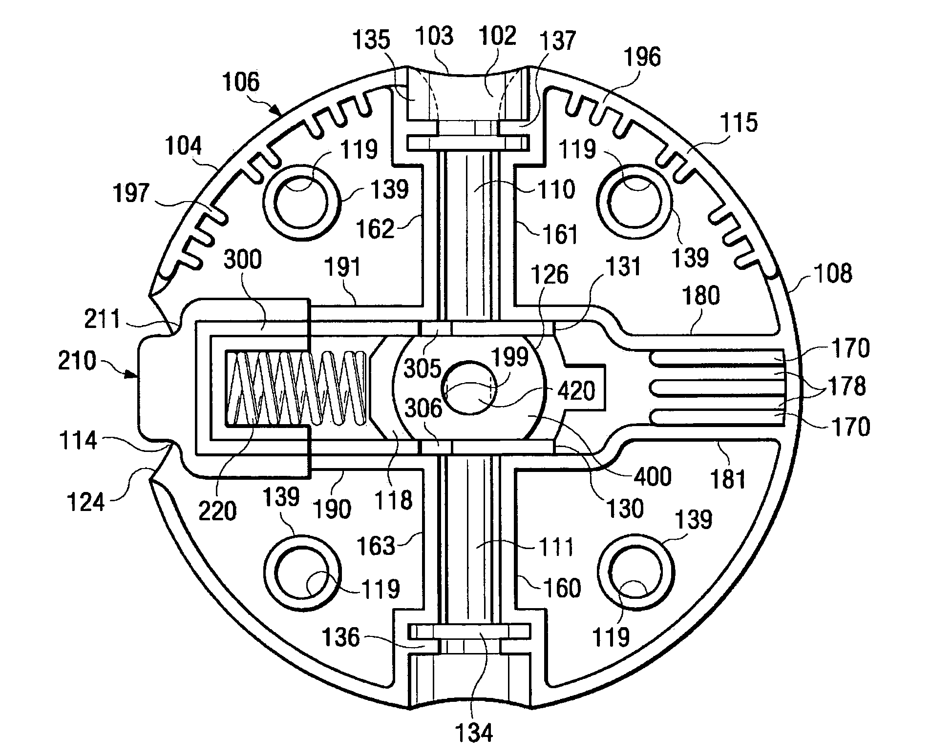
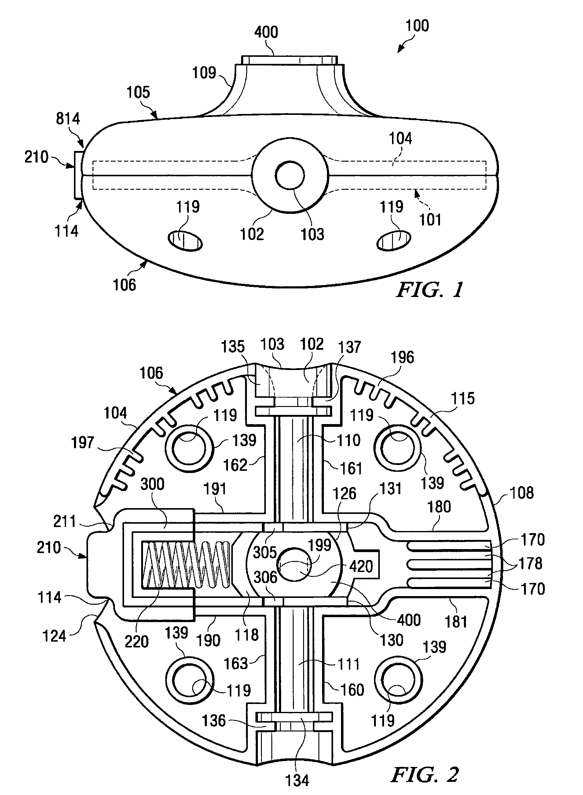
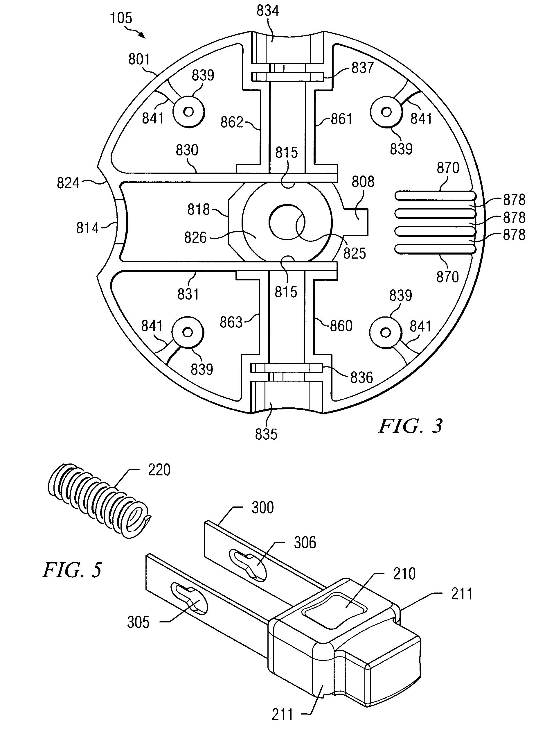
[0039]Referring to FIGS. 1, 2 and 3, a preferred embodiment of a head for a rotary line trimmer is shown. Head 100 has a generally disk-like housing formed by upper cover 105 and lower cover 106. The housing in the preferred embodiment is constructed of injection molded nylon. Other materials with suitable strength and rigidity to maintain the positions of internal parts can be used such as fiberglass and polypropylene. Head 100 has two diametrically opposed openings where the single cutting line protrudes. Head 100 mounts on the threaded rotating drive shaft of a typical rotary line trimmer by way of an arbor 400. Arbor 400 is provided with an arbor hole 420 and is threaded to accept the lower portion of the line trimmer drive shaft. In an alternate embodiment the drive shaft passes through the head by way of a shaft hole and is secured to the head with a shoulder bolt (not shown). Upper cover 105 has a rounded exterior shape and a generally flat top surface including arbor hub 109...


PUM


Abstract

An improved head for a flexible line trimmer apparatus is provided. The improved head includes a metal tubing that extends through the head and surrounds a cutting line of selected length. The tubing is provided with a flared exit portal increasing the efficiency of the head. The contact surface eliminates the possibility of the cutting line fusing to plastic surfaces due to heating caused by friction. The head is surrounded with an interior perimeter counterweight to store kinetic energy on each end having a parabolic surface of revolution concentric with the axis of the tubing. A replaceable cartridge is provided to increase the ease of maintenance and the useful life of the head.

Description

FIELD OF THE INVENTION[0001]This invention relates to flexible rotary line trimmers. In particular, this invention relates to a balanced head for a rotary line trimmer in which a metal tube is provided in the head surrounding the trimming line to prevent frictional welding and premature failure of the line and the head. Further the invention relates to a removable cartridge that creates a path for the trimming cutting line and which may be easily removed for cleaning and periodic maintenance.BACKGROUND OF THE INVENTION[0002]Rotary line trimmers are widely used for cutting grass, weeds and other plants in the upkeep of lawns and generally clearing vegetation. Line trimmers are typically characterized by a flexible nylon trimming line attached to a rotatable head. The head is attached to a motor shaft which is rotated at high speeds, typically by trigger operation of a small gasoline engine or electric motor. When the head is rotated, the rotating trimming line serves as a cutting bla...

Claims


Application Information

Patent Timeline
Patent Type & Authority Patents(United States)
IPC IPC(8): A01D34/416
CPCA01D34/4166
Inventor MOORE, MARK R.
Owner MOORE MARK R
Learn More