Bi-facial photovoltaic power generation module

a power generation module and facial photovoltaic technology, applied in the field of solar power generation, can solve the problems of reducing the production cost of cells, reducing the application scope of renewable energy, and reducing the power generation efficiency of the module per unit area, so as to improve the power generation efficiency of the modul

Active Publication Date: 2020-05-19
GU JINJIE +2
View PDF4 Cites 0 Cited by
  • Summary
  • Abstract
  • Description
  • Claims
  • Application Information

AI Technical Summary

Benefits of technology

[0005]In order to solve the above problems, the present invention provides a bi-facial photovoltaic power generation module, which simultaneously generates power on front and back sides thereof and improves the power generation efficiency of the module per unit area.
[0016]Compared with the prior art, firstly, by installing the solar cell string in the transparent box, on the one hand, the cell string is less prone to scratch, premature aging, damage and the like during use, thus playing a good role in protecting the cells, and on the other hand, it is beneficial for the cell string to better absorb light energy; secondly, the cell string is formed by connecting several N-type bi-facial monocrystalline silicon cells in series or in parallel and is vertically installed on the mounting base, so that both sides of the cell string can generate power, the generated output of the module can be improved, the power generation efficiency of the module per unit area can be improved, and the cost per kilowatt hour of photovoltaic power generation can be effectively reduced.

Problems solved by technology

Under the background of increasingly serious energy shortage and environmental pollution, the development of renewable energy has become a major global issue.
However, the higher production cost restricts its application scope.
With the drastic reduction of government subsidies, it is an urgent problem for all manufacturers to reduce the production cost of cells and improve the power generation efficiency.
More than 85% of the commercial solar cell market is still occupied by crystalline silicon solar cell products, and the cost-performance competition around efficiency and cost is very fierce.
Meanwhile, with the increasing global installed capacity of solar energy, there is less and less photovoltaic land available.

Method used


Image

  • Bi-facial photovoltaic power generation module
  • Bi-facial photovoltaic power generation module
  • Bi-facial photovoltaic power generation module

Examples


Embodiment Construction

[0021]The present invention will be described in detail as below with reference to the accompanying drawings by the specific embodiments.

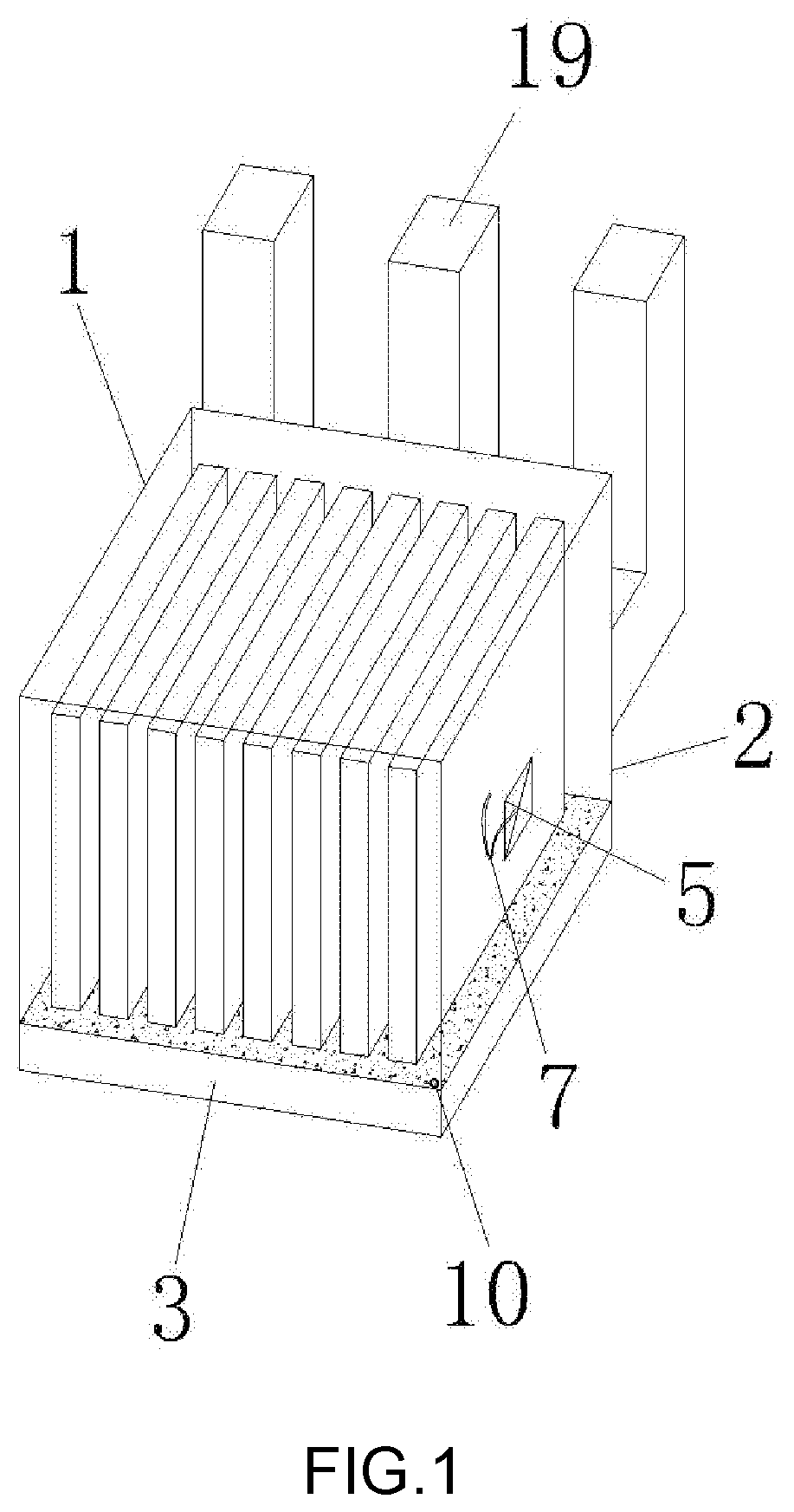
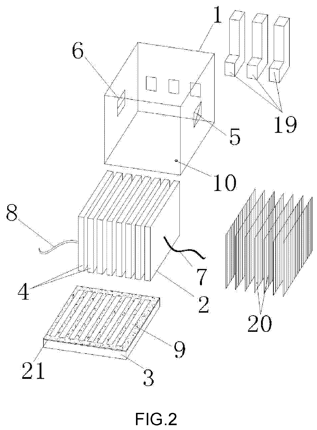
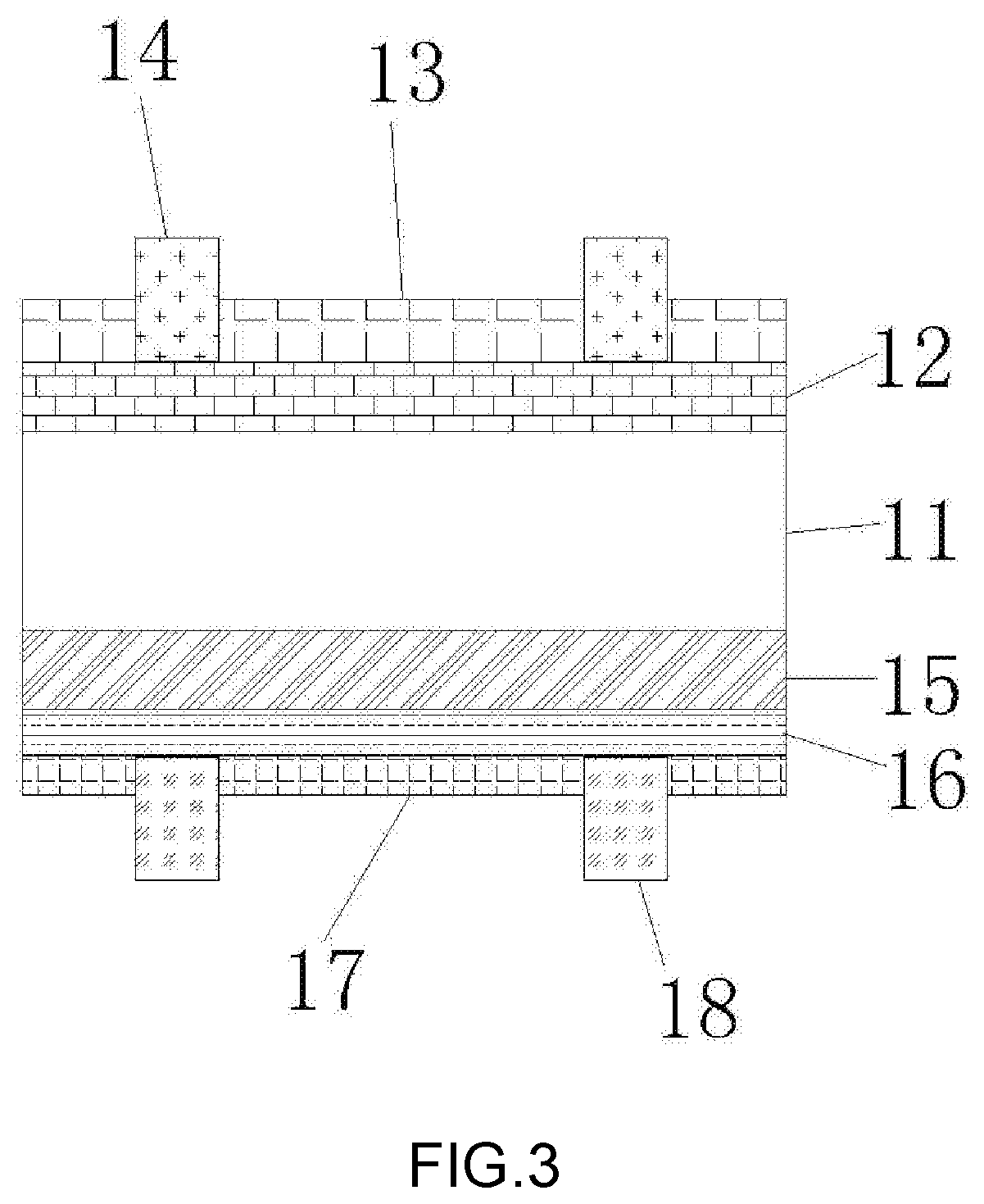
[0022]Referring to FIG. 1 to FIG. 3, The present invention relates to a bi-facial photovoltaic power generation module, including a transparent box 1, and a cell string 2 and a mounting base 3 which are installed inside the transparent box 1, wherein the transparent box 1 is internally provided with a positive terminal 5 and a negative terminal 6 passing through two side faces of the transparent box 1, respectively, the cell string 2 is formed by connecting several N-type bi-facial monocrystalline silicon cells 4 in series or in parallel, with one end of the cell string 2 connected to a positive wire 7 and the other end thereof connected to a negative wire 8; the positive wire 7 is welded on the positive terminal 5 and the negative wire 8 is welded on the negative terminal 6; and the mounting base 3 is provided with several parallel strip-shaped sl...


PUM

PropertyMeasurementUnit
diameteraaaaaaaaaa
power generation efficiencyaaaaaaaaaa
thicknessaaaaaaaaaa

Abstract

The present invention discloses a bi-facial photovoltaic power generation module, comprising a transparent box, and a cell string and a mounting base which are installed inside the transparent box, wherein the transparent box is provided with a positive terminal and a negative terminal, the cell string is formed by connecting several bi-facial cells in series or in parallel with both ends of the cell string respectively provided with a positive wire and a negative wire welded on the positive terminal and the negative terminal, and the mounting base is provided with strip-shaped slots in which the bi-facial cells can be plugged. According to the present invention, the module can simultaneously generate power on front and back sides thereof and improve its power generation efficiency per unit area.

Description

BACKGROUND OF THE INVENTION[0001]The present invention relates to the technical field of solar power generation, in particular to a bi-facial photovoltaic power generation module.[0002]Under the background of increasingly serious energy shortage and environmental pollution, the development of renewable energy has become a major global issue. Solar cells, also known as “solar chips” or “photocells”, are photoelectric semiconductor chips that generate electricity directly by making use of the sunlight. As long as such solar cell is illuminated under certain illumination conditions, it can output voltage in an instant and generate current in the case of a circuit. Therefore, the use of solar energy is an important direction for developing renewable energy sources. However, the higher production cost restricts its application scope. With the drastic reduction of government subsidies, it is an urgent problem for all manufacturers to reduce the production cost of cells and improve the pow...

Claims


Application Information

Patent Timeline
Patent Type & Authority Patents(United States)
IPC IPC(8): H01L31/0465H01L31/02H01L31/0224H01L31/075H01L31/054H01L31/0216H01L31/052H01L31/0203H01L31/042H01L31/048H01L31/068H01L31/028
CPCH01L31/075H01L31/028H01L31/02013H01L31/042H01L31/022425H01L31/0465H01L31/0543H01L31/0521H01L31/054H01L31/0684H01L31/02168Y02E10/52Y02E10/547Y02E10/548
Inventor GU, JINJIEWANG, SHUQINGU, LETIAN
Owner GU JINJIE
Why Eureka
Try Eureka