
Method for operating a fuel cell and a fuel cell arrangement

a fuel cell and hybrid arrangement technology, applied in the direction of machines/engines, electrical equipment, mechanical equipment, etc., can solve the problem of very vulnerable fuel cells to internal temperature gradients, and achieve the effect of prolonging the lifetime of the catalyst of the fuel cell and prolonging the life of the whole fuel cell hybrid arrangemen

Active Publication Date: 2015-09-15
VOLVO TRUCK CORP
View PDF13 Cites 0 Cited by
  • Summary
  • Abstract
  • Description
  • Claims
  • Application Information

AI Technical Summary

Benefits of technology

This approach prolongs the lifetime and performance of the fuel cell hybrid arrangement by minimizing exothermic conditions during startup, enabling power generation during the startup phase without damaging the components, and reducing the risk of catalyst degradation.

Problems solved by technology

Such a fuel cell is very vulnerable to internal temperature gradients which espedally occur during the start up procedure due to different thermal expansion properties of the different materials within the fuel cell.

Method used


Image

  • Method for operating a fuel cell and a fuel cell arrangement
  • Method for operating a fuel cell and a fuel cell arrangement
  • Method for operating a fuel cell and a fuel cell arrangement

Examples


first embodiment

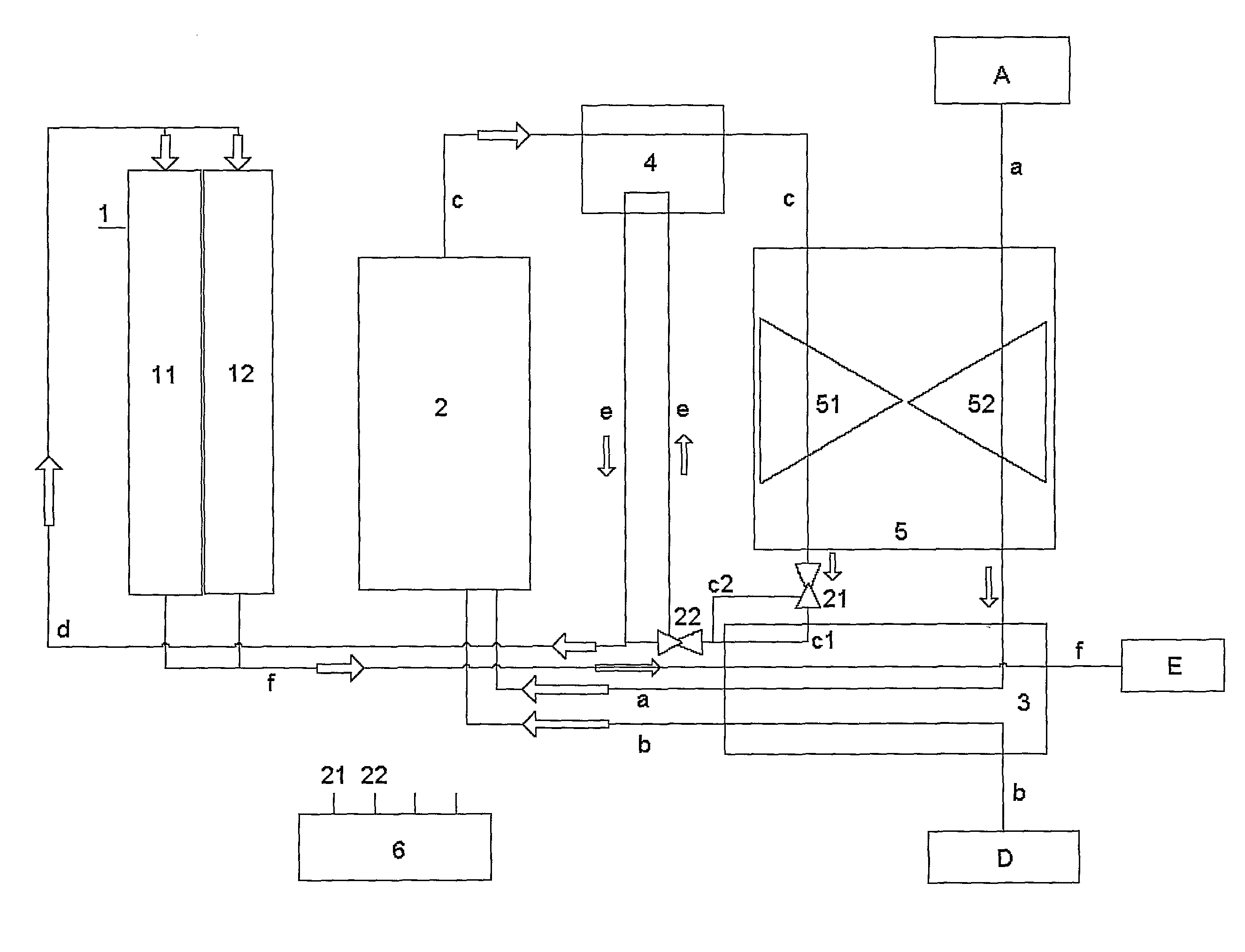
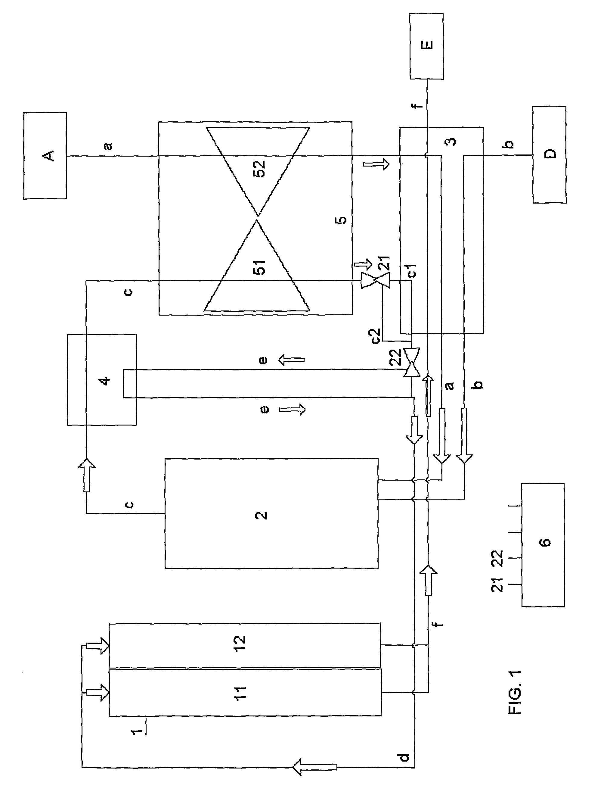
[0026]FIG. 1 shows the method according to the invention during a first or initial start phase, which starts when switching-on the fuel cell hybrid arrangement and which is explained in the following.

[0027]Substantially, the first or initial start phase is provided for subjecting fuel to an exothermic reaction with oxygen in the burner unit 2 (which preferably is a catalytic burner unit or a conventional burner unit) in order to warm up and passively heat the fuel cell 1 by means of the heat of the output gases from the burner unit 2.

[0028]More in detail, during the first or initial start phase air is supplied from the air feed A via a first line a which leads through the compressor 52 of the turbine unit 5, in which it is compressed, and through the first heat exchanger 3 for receiving heat into a first input of the burner unit 2. Furthermore, fuel (preferably DME, see above) is supplied from the fuel feed D via a second line b through the first heat exchanger 3 for receiving heat ...

second embodiment

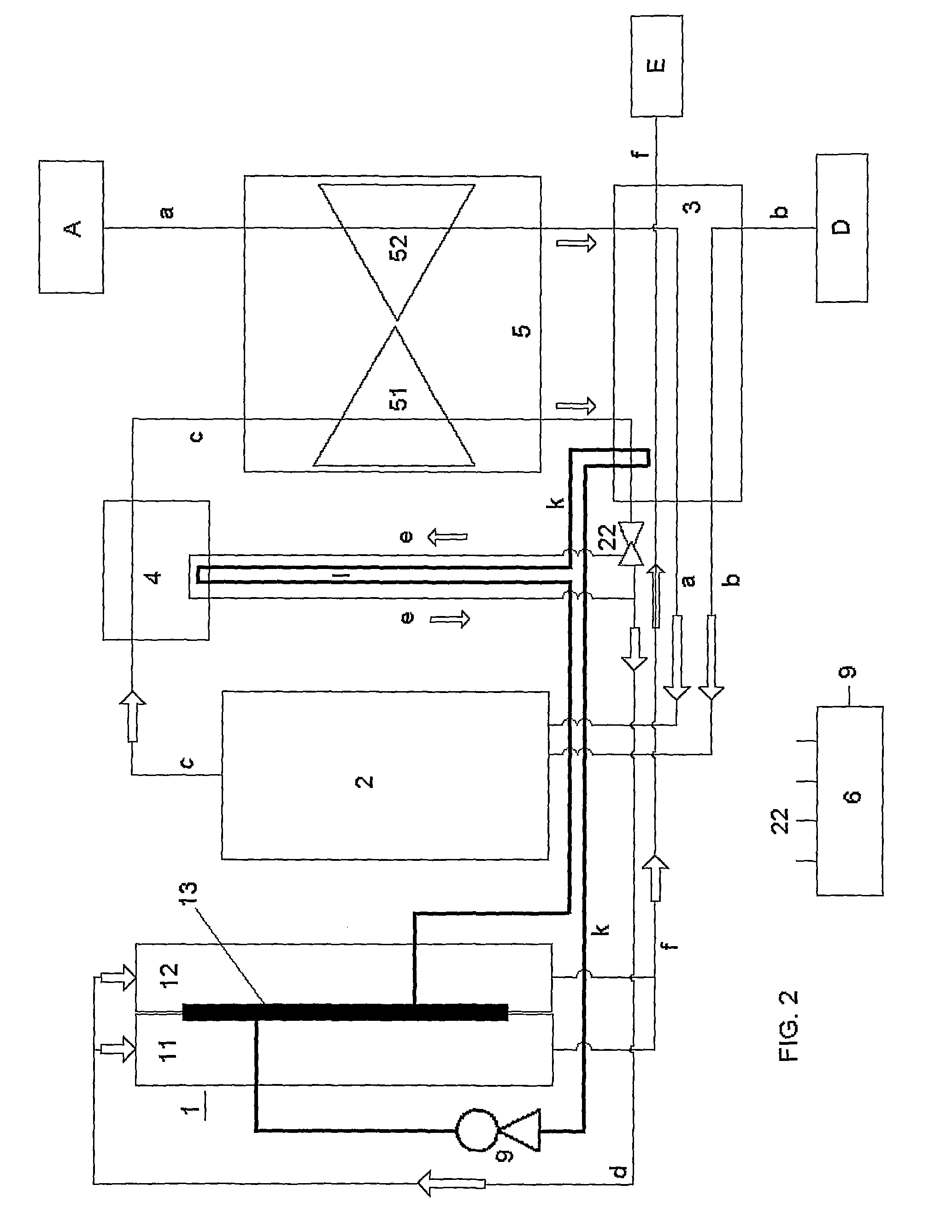
[0042]The substantial difference between the first and the invention according to the FIGS. 1 and 2 is, that the fuel cell hybrid arrangement according to FIG. 2 is provided with an additional heat transportation system generally comprising channels or pipes and manifolds which are passed through the first and / or the second heat exchanger 3, 4 for receiving heat and which are passed through a separate heating chamber or compartment 13 within the fuel cell 1, preferably next to the anode, for releasing heat and additionally heating-up the fuel cell 1.

[0043]According to FIG. 2, exemplarily a seventh line k and an eighth line I (the latter line I connecting the second heat exchanger 4 to the additional heat transportation system) as well as a pump unit 9 for conveying a heat exchange fluid or coolant medium through the lines k, I and through the cooling chamber or compartment 13 (only schematically indicated) is provided, wherein the seventh line k receives heat from the first heat exc...


PUM

PropertyMeasurementUnit
temperaturesaaaaaaaaaa
temperatureaaaaaaaaaa

Abstract

A method for operating, especially for starting, a fuel cell such as a solid oxide fuel cell (SOFC) is disclosed which method includes a starting operation with a first or initial start phase and an optional second or intermediate start phase which is initiated when the fuel cell has reached a predetermined medium temperature below a steady state operational temperature range, before a steady state operation is activated. During the first or initial start phase fuel is subjected to an exothermic reaction with oxygen in a burner unit and output gases from the burner unit are used to warm up and passively heat the fuel cell. Furthermore, a fuel cell arrangement comprising a fuel cell, especially a SOFC hybrid system, for conducting this method is disclosed.

Description

BACKGROUND AND SUMMARY[0001]The invention relates to a method for operating, especially for starting, a fuel cell like especially a solid oxide fuel cell (SOFC). The invention further relates to a fuel cell arrangement comprising such a fuel cell, especially a SOFC hybrid system, for conducting this method.[0002]Solid oxide fuel cells are used to convert fuel, such as hydrogen or a hydrogen rich compound, and oxygen to electric power, heat and hot output gases. The fuel is fed to an anode compartment of the fuel cell and oxygen is supplied by ambient or compressed air to a cathode compartment of the fuel cell.[0003]Such a fuel cell is very vulnerable to internal temperature gradients which espedally occur during the start up procedure due to different thermal expansion properties of the different materials within the fuel cell.[0004]JP 2001351665 discloses a composite electric generator and a method for starting such a generator, wherein the composite electric generator is composed ...

Claims


Application Information

Patent Timeline
Patent Type & Authority Patents(United States)
IPC IPC(8): H01M8/04H01M8/02H01M8/12
CPCH01M8/04701H01M8/04111H01M8/04268H01M8/04753H01M8/04776H01M2008/1293Y02E60/50Y02E60/525
Inventor JOHANSEN, LARSMARDBERG, PETER JOZSA
Owner VOLVO TRUCK CORP
Learn More