UV sterilizer

Inactive Publication Date: 2007-11-29
UV LIGHT SCI GROUP
View PDF7 Cites 54 Cited by
  • Summary
  • Abstract
  • Description
  • Claims
  • Application Information

AI Technical Summary

Benefits of technology

[0004] In accordance with an aspect of the present invention there is provided a sterilizer. The sterilizer includes a housing that is opaque to Ultra-Violet radiation. The housing has an interior and an access aperture to allow ingress of an object to be sterilized and a C-band Ultra-Violet radiation transparent support structure mounted in the interior of the housing to support the object to be sterilized. The sterilizer further includes a plurality of C-band Ultra-Violet radiation sources mounted in the interior of the housing to surround the object to be sterilized on at least four sides and a plurality of C-band Ultra-Violet radiation transparent separators mounted in the interior of the housing to separate one or more of the plurality of C-band Ultra-Violet radiation sources from the object to be sterilized.

Problems solved by technology

Furthermore, the object to be sterilized is often required to rest on a support during the sterilization process.

Method used


Image

  • UV sterilizer
  • UV sterilizer
  • UV sterilizer

Examples


Embodiment Construction

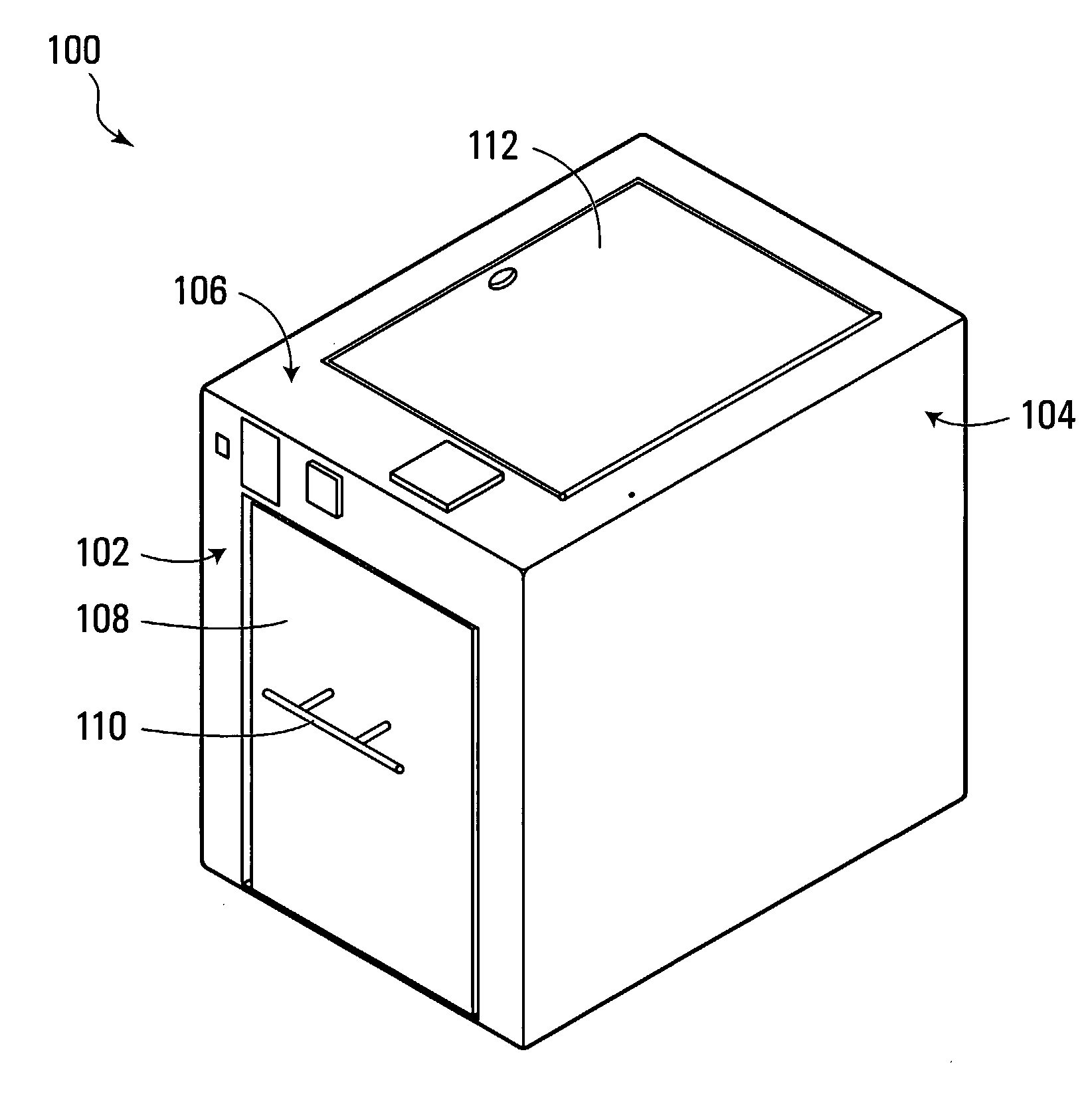
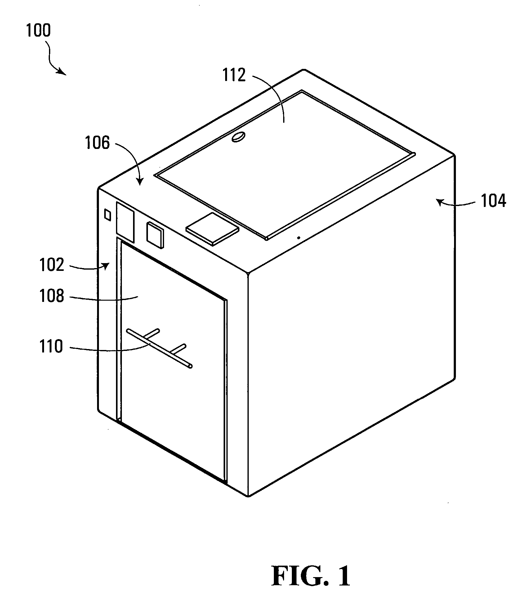
[0013] As illustrated in FIG. 1, a sterilizer 100 is formed as a box, or housing, having left and right sides, front and back sides, and top and bottom sides, where all side are opaque to UVC radiation. In the front, right perspective view of FIG. 1, the front side 102, right side 104 and top side 106 are in view. The front side 102 includes a front door 108 with a door handle 110. The top side 106 includes a top access door 112.

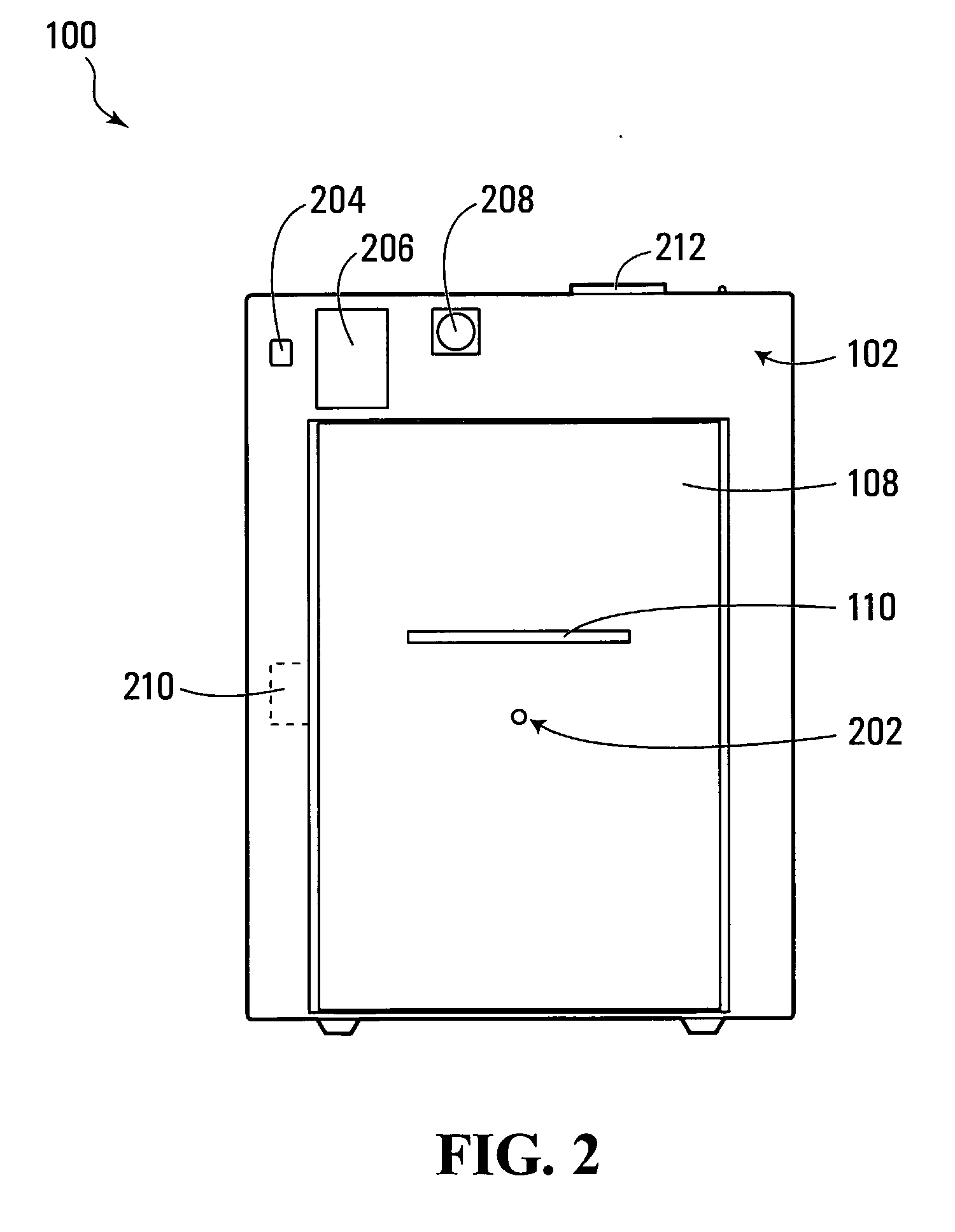
[0014] As illustrated in the elevation view of FIG. 2, the front door 108 includes a door safety switch 202 and a door lock 210. Additionally, in the portion of the front side 102 that is above the front door 108, various control elements are evident, including a master lamp power switch 204, a lamp monitor 206 and a timer 208. A fan exit port 212 is illustrated protruding slightly from the top side 106 of the sterilizer 100.

[0015] In the front elevation sectional view of FIG. 3, UVC lamps, which are individually or collectively referenced as 302, are illu...


PUM


Abstract

A box-type sterilizer using C-band Ultra-Violet (UVC) radiation is based on a hollow rectangular box with a door on one end. Mounted proximate to the interior surfaces of the box are lamps that, when powered, produce UVC radiation. In operation, an object to be sterilized is placed inside the box, the door is closed and the lamps are briefly powered. Any DNA-based organisms present on the object to be sterilized are killed by the UVC radiation. Cross tubes of quartz glass, which are transparent to UVC radiation, are used to support the object to be sterilized and separate the object to be sterilized from the lamps on the bottom interior surface. Cross tubes of quartz glass are also used to separate the object to be sterilized from the lamps on the other interior surfaces.

Description

FIELD OF THE INVENTION [0001] The present invention relates to sterilization using Ultra-Violet (UV) radiation and, more particularly, to a box-type UV sterilizer. BACKGROUND [0002] UV sterilizers are well known for use in sterilizing all manner of objects including contact lenses, combs and safety goggles. Often only a single source of radiation is employed and, as such, there are often areas on an object to be sterilized that are shadowed from the UV radiation produced from the single source. Furthermore, the object to be sterilized is often required to rest on a support during the sterilization process. If the support is not transparent to the UV radiation, the support also contributes to shadowing the object to be sterilized from the UV radiation. SUMMARY [0003] A sterilizer using C-band Ultra-Violet (UVC) radiation comprising a hollow housing with an aperture is disclosed in this specification. Mounted proximate to the interior surfaces of the housing are radiation sources that...

Claims


Application Information

Patent Timeline
Patent Type & Authority Applications(United States)
IPC IPC(8): B01J19/08
CPCA61L2/10
Inventor MILLIKIN, STEVE
Owner UV LIGHT SCI GROUP
Why Eureka
Try Eureka