

Gynecological Instrument
- Summary
- Abstract
- Description
- Claims
- Application Information
AI Technical Summary
Benefits of technology
Problems solved by technology
Method used
Image

Examples
Example
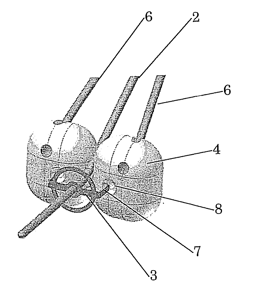
[0020] Finally, FIG. 5 schematically shows a second embodiment in which the source guide tubes comprise a ring applicator tube 9, of different dimensions 10. The flange-shaped stopping means (e.g., stop 3) is arranged for insertion into the central opening of the ring applicator tube 9 and thus fixates the ring applicator tube 9 relative to the intrauterine tube 2. The conventional stop does not do this and only serves for axial positioning of the intrauterine tube 2.
[0021] Although the invention has been elucidated with reference to the examples shown in the drawings, the invention is not limited thereto but may also comprise variations or modifications without deviating from the spirit of the invention. The scope of the invention is determined by the following claims.
PUM
 Abstract
Description
Claims
Application Information