
Tape printing device

Active Publication Date: 2006-04-04
BROTHER KOGYO KK
View PDF17 Cites 5 Cited by
  • Summary
  • Abstract
  • Description
  • Claims
  • Application Information

AI Technical Summary

Benefits of technology

[0007]The present invention is advantageous in that the above-mentioned problem can be solved. According to the invention, there is provided an improved tape printing device that is easy to operate, easy to hold with a hand and easy to input printing data by pressing the character input keys or the like with the hand that holds the device.
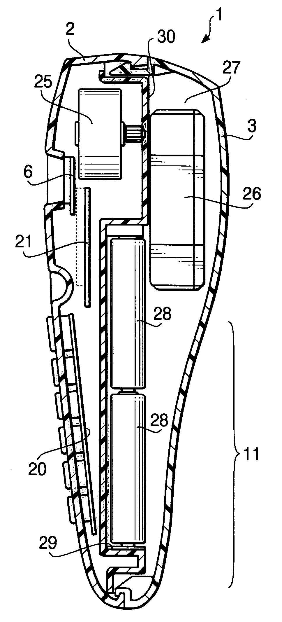
[0008]Further, according to the invention, there is provided a tape printing device in which the tape cassette and the battery holder are arranged such that the tape cassette and a part of the battery holder overlaps in the vertical direction so that the gripping portion can be made in a form easy to hold, and so that the body size of the device in the longitudinal direction can be reduced easily.

Problems solved by technology

In the conventional tape printing device described above, the width of the case of the device is relatively wide since the batteries are arranged in parallel with the width direction of the device body, and hence the portion gripped by a hand is also wide, which makes it difficult to hold the device body with one hand.
Further, the wide gripping portion of the device body makes it difficult to operate keys such as character input keys by the same hand that holds the tape printing device.
That is, in such a device, it is necessary to press the character input keys, for example, by the right hand while holding the tape printing device with the left hand, resulting in bad operability.

Method used


Image

  • Tape printing device
  • Tape printing device
  • Tape printing device

Examples


Embodiment Construction

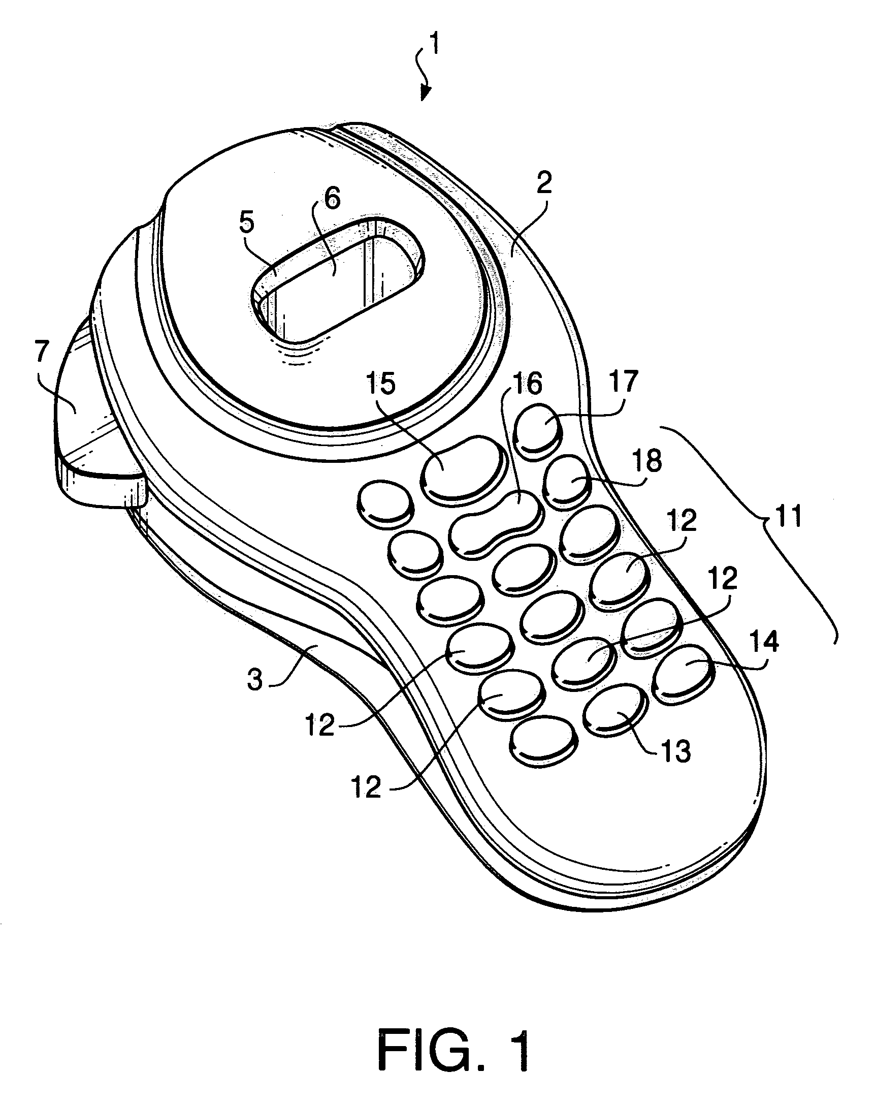
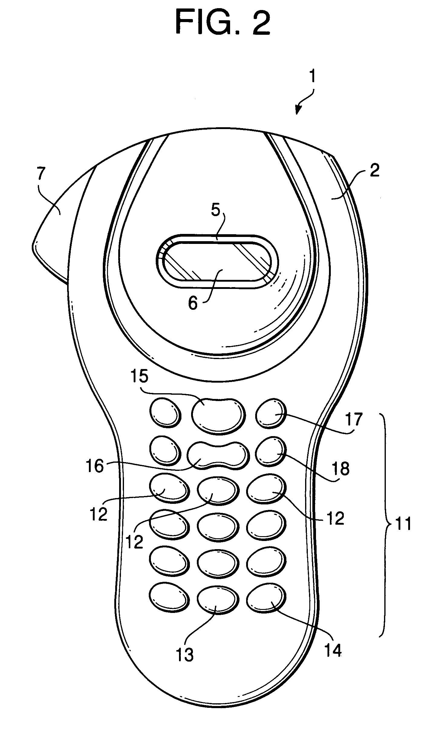
[0046]Hereinafter, a tape printing device 1 according to an embodiment of the invention will be described in detail with reference to the accompanying drawings.

[0047]First, the general configuration of the tape printing device 1 will be described with reference to FIGS. 1 through 4.

[0048]As shown in FIGS. 1 through 4, the tape printing device 1 has a body 2 made of synthetic resin and a back cover 3 made of synthetic resin. The back cover 3 is detachably attached to the body 2 so that it covers the rear side, which is a side opposite to a front side that faces a user using the tape printing device 1, of the body 2. As shown in FIG. 2, the tape printing device 1 is longer in an up and down direction in FIG. 2 than in a width direction (i.e., a right and left direction in FIG. 2). A substantially upper half of the body 2 in the longitudinal direction thereof is formed to have a relatively round shape when viewed from the front (as shown in FIG. 2). A window 5 is opened at a substantia...


PUM


Abstract

A tape printing device is provided with a device body. A cassette holding section is formed on one end side portion in the longitudinal direction of the body. A battery holding section is formed on the other end side portion of the device body. A plurality of batteries are accommodated in the battery holding section. At least two batteries are aligned such that the longitudinal direction of the batteries is substantially parallel with the longitudinal direction of the device body. The tape printing device further includes a printing system, and a driving system that feeds a tape-form recording medium. In the tape printing device, the device body has a gripping portion formed on the other end side portion of the device body. The width of the gripping portion of the device body is narrower than the width of the cassette holding section.

Description

BACKGROUND OF THE INVENTION[0001]The present invention relates to a portable tape printing device for printing characters / letters on a tape-form recording medium.[0002]Conventionally, various portable tape printing devices are proposed. An example of the portable tape printing device is configured to have a body in which a tape cassette holding a tape-form recording medium (hereinafter simply referred to as a tape) is accommodated. A platen roller driven by a driving motor powered by batteries is provided in the device. The tape is printed by a printing mechanism and discharged from the device.[0003]U.S. Pat. No. 5,758,980 discloses such a tape printing device. According to the disclosure of the publication, a control circuit board and the tape cassette are arranged inside a case of the tape printing device such that they substantially overlap in the vertical direction, and a cutout portion is formed at one end of the control circuit board in a longitudinal direction thereof. The dr...

Claims


Application Information

Patent Timeline
IPC IPC(8): B41J3/36B41J29/00B41J3/407B41J3/46
CPCB41J3/4075
Inventor KONDO, HAKUDAI
Owner BROTHER KOGYO KK
Learn More