Electrical Panel Input Interlock Assembly

a technology of input interlocking and electrical panels, applied in the direction of contact, electrical apparatus, contact engagement, etc., can solve problems such as failure of devices

Active Publication Date: 2007-12-06
RELIANCE CONTROLS
View PDF13 Cites 11 Cited by
  • Summary
  • Abstract
  • Description
  • Claims
  • Application Information

AI Technical Summary

Benefits of technology

[0010]The present invention is directed to a main power switch interlock assembly that prevents inadvertent simultaneous electrical connection of both a utility power input and an input from an alternate power supply, such as a generator, to a breaker panel, and controls actuation of utility and alternate power supply neutral switches.

Problems solved by technology

Having normal current flow on the grounding conductor limits the ability of the grounding conductor to perform its safety function, and is therefore undesirable.
Furthermore, it is important to control the sequence of operation of the generator and utility neutral switches when switching between power sources, since supplying power to a device without a neutral may result in failure of the device due to an unpredictable voltage being supplied to the device.

Method used


Image

  • Electrical Panel Input Interlock Assembly
  • Electrical Panel Input Interlock Assembly
  • Electrical Panel Input Interlock Assembly

Examples


Embodiment Construction

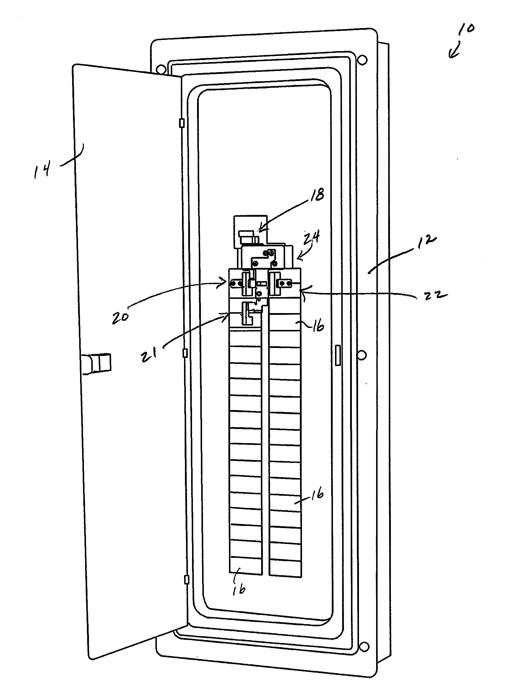
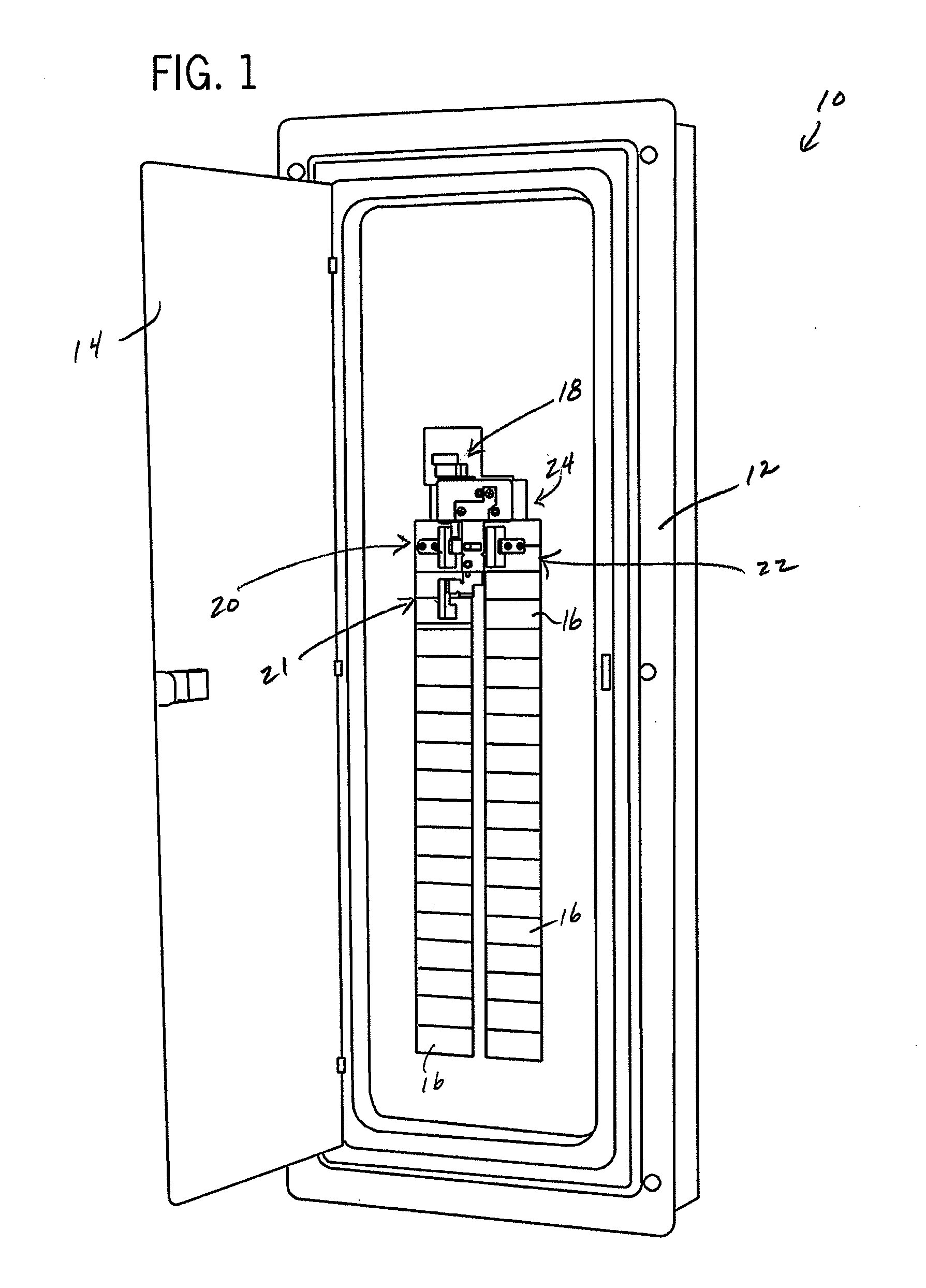
[0026]FIG. 1 shows a load center assembly 10 according to one embodiment of the present invention, which is configured to supply power to a series of electrical circuits from one of at least two power sources. Representatively, load center assembly 10 controls the supply of power to the electrical circuits from a primary power supply, such as utility power, and an alternate or secondary power source which is adapted to supply power in the event power from the primary power supply is unavailable. Typically, the alternate or secondary power source is an electrical generator, although it is understood that any other source of secondary or alternate power may be employed. The following description utilizes terminology which makes reference in various instances to a generator, and it is understood that such terminology is used for the sake the convenience and that the term “generator” is meant to encompass any secondary or alternate power source, and is not limited to a generator as the ...


PUM


Abstract

A system and method of interlocking a plurality of electrical panel switches includes an interlock assembly having an interlock. The interlock has a first position that allows connection of one of utility power and power from an alternate power supply, such as a generator, to the electrical panel and prevents connection of the other of the utility power and generator power. The interlock has a second position that allows connection of the other of the utility power and generator power and prevents connection of one of the utility power and generator power to the electrical panel. The interlock also is constructed to control the positioning and sequence of operation of neutral connections between the power sources and the electrical panel.

Description

CROSS-REFERENCE TO RELATED APPLICATION[0001]This application claims the benefit of U.S. Ser. No. 60 / 804,016, filed Jun. 6, 2006, the disclosure of which is incorporated herein by reference.BACKGROUND OF THE INVENTION[0002]The present invention relates generally to electrical panels and, more particularly, to a power supply or input interlock assembly constructed to electrically isolate different inputs connected to an electrical panel.[0003]Electrical panels, breaker boxes, or load centers frequently include a main contactor, switch, or breaker, which electrically isolates a series of load breakers from a utility power input. Occasionally, such load panels are configured to receive another input power source, such as from a generator, to provide electrical power to the individual loads in the event of a utility power failure. During interruption of utility power, the generator supplies power to the load center, which the load center distributes to the selected or designated circuits...

Claims


Application Information

Patent Timeline
Patent Type & Authority Applications(United States)
IPC IPC(8): H01H9/26H01H9/20
CPCH01H2300/018H01H9/26
Inventor FLEGEL, MICHAEL O.
Owner RELIANCE CONTROLS
Why Eureka
Try Eureka