Method and apparatus for retrofitting work vehicle with blade position sensing and control system
- Summary
- Abstract
- Description
- Claims
- Application Information
AI Technical Summary
Benefits of technology
Problems solved by technology
Method used
Image

Examples
Example
DETAILED DESCRIPTION OF THE DRAWINGS
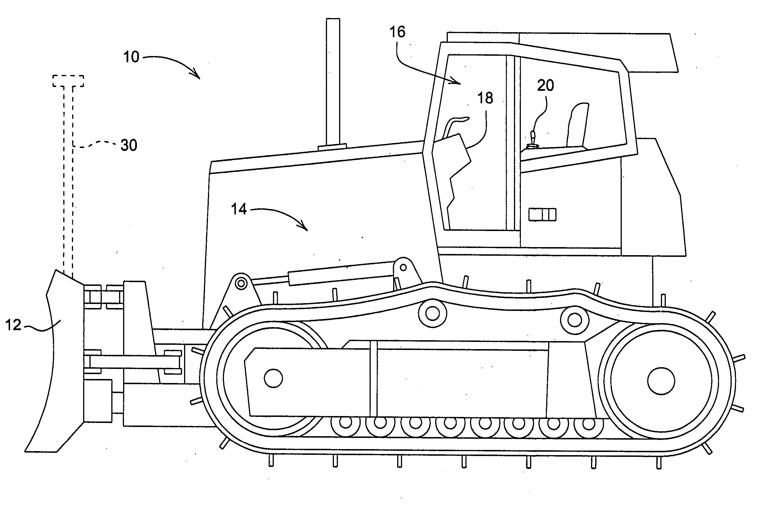
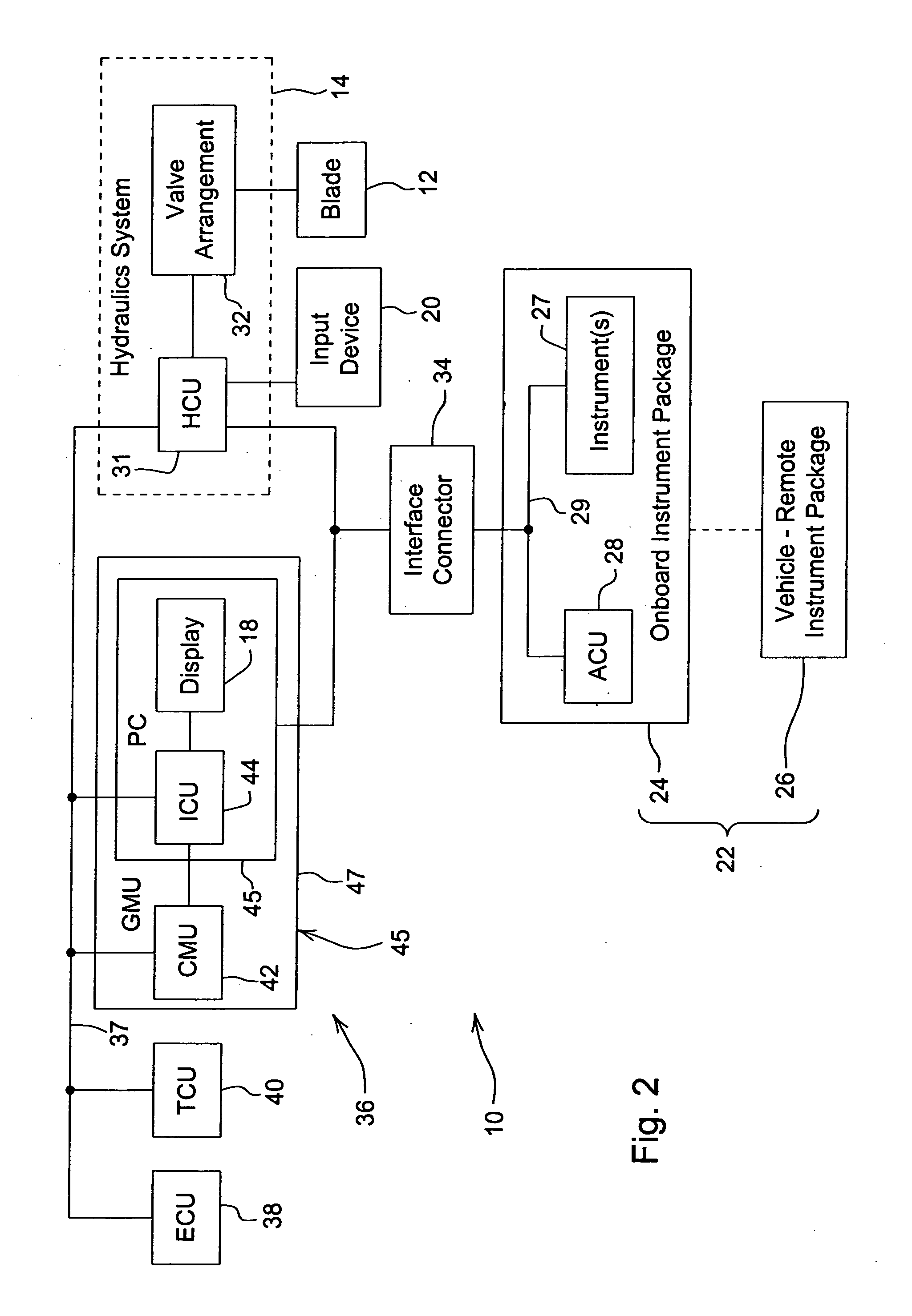
[0010] Referring to FIG. 1, a work vehicle 10 has a blade 12 which may be used for moving material (e.g., dirt, rock) to grade a worksite according to a predetermined grading plan. To facilitate achievement of the desired grade across the worksite, the work vehicle 10 may be retrofitted with any of a number of blade position sensing and control systems. Such systems may be in the form of, for example, a laser-based blade position sensing and control system, a GPS-based blade position sensing and control system, a sonic-based blade position sensing and control system, combinations thereof, or other suitable system. The work vehicle 10 is configured to be retrofitted with any of such systems without modification of the hydraulics system 14 of the vehicle 10.
[0011] Illustratively, the vehicle 10 is depicted as a crawler dozer. However, it is to be understood that the vehicle 10 may be configured as other types of work vehicles with earth-moving or ...
PUM
 Abstract
Description
Claims
Application Information