Supercharge Your Innovation With Domain-Expert AI Agents!

Device and method for controlling ignition timing of internal combustion engine

Active Publication Date: 2007-12-20
TOYOTA JIDOSHA KK +2
View PDF11 Cites 1 Cited by
  • Summary
  • Abstract
  • Description
  • Claims
  • Application Information

AI Technical Summary

Benefits of technology

[0009]An object of the present invention is to provide a device and the like for controlling ignition timing of an internal combustion engine that can suppresses excessive retarding of ignition timing.
[0011]According to the configuration, a crank angle of the internal combustion engine is detected. A waveform of vibration of the internal combustion engine in a predetermined range of the crank angle is detected. A first value representing a degree of agreement between the waveform and a waveform model is calculated. Furthermore, a second value representing magnitude of the vibration generated in the internal combustion engine is calculated. Based on a combination of the first value and the second value, it is determined whether or not knocking has occurred in the internal combustion engine. There exists a case where the magnitude of the vibration may be equivalent to magnitude at the time of knocking even though the waveform of the vibration of the internal combustion engine is not similar to the waveform model. There also exists a case where the waveform of the vibration of the internal combustion engine may be similar to the waveform model even though the magnitude of the vibration is small. In any of these cases, it can be concluded that knocking has not occurred. Accordingly, it is determined that knocking has not occurred in at least one of the case where the first value satisfies a first condition and the case where the second value satisfies a second condition. For example, it is determined that knocking has not occurred in at least one of the case where a condition that the first value is smaller than a first threshold value is satisfied, and the case where a condition that the second value is smaller than a second threshold value is satisfied. It becomes thereby possible to reduce erroneous determination that knocking has occurred while knocking has not occurred. Accordingly, it becomes possible to suppress erroneous implementation of ignition timing retard, which should be implemented at the time of knocking. Consequently, excessive retarding of ignition timing can be suppressed. Furthermore, if it is determined that knocking has occurred, the internal combustion engine is controlled such that the ignition timing is retarded by an amount corresponding to a combination of the first value and the second value. For example, the ignition timing is retarded by a smaller amount as the first value becomes smaller, or the ignition timing is retarded by a smaller amount as the second value becomes smaller. It becomes thereby possible to minutely set a retarding amount of ignition timing at the time of knocking. Accordingly, it becomes possible to provide a device for controlling ignition timing of the internal combustion engine that can suppresses excessive retarding of the ignition timing.
[0013]According to the configuration, a maximum value of the magnitude of the vibration in the predetermined range is divided by a value set as a reference of the magnitude of the vibration of the internal combustion engine to thereby calculate the second value. It becomes thereby possible to precisely determine whether or not knocking has occurred by using the maximum value of the magnitude, which may significantly be different between the case where knocking has occurred and the case where knocking has not occurred. Accordingly, it becomes possible to precisely determine whether or not knocking has occurred.
[0015]According to the configuration, it is determined that knocking has not occurred in at least one of the case where the condition that the first value is smaller than the first threshold value is satisfied and the case where the condition that the second value is smaller than the second threshold value is satisfied. In other words, it is determined that knocking has not occurred in at least one of the case where the detected waveform is considered not to be similar to the waveform model, and the case where the magnitude of the vibration is considered to be small. Accordingly, it becomes possible to reduce erroneous determination that knocking has occurred while knocking has not occurred.
[0017]According to the configuration, the ignition timing is retarded by a smaller amount as the first value becomes smaller. In other words, the ignition timing is retarded by a smaller amount as the degree of agreement between the detected waveform and the waveform model becomes lower. It becomes thereby possible to minutely set a retarding amount of the ignition timing at the time of knocking. Accordingly, excessive retarding of the ignition timing can be suppressed.
[0019]According to the configuration, the ignition timing is retarded by a smaller amount as the second value becomes smaller. In other words, the ignition timing is retarded by a smaller amount as the magnitude of the vibration becomes smaller. It becomes thereby possible to minutely set a retarding amount of the ignition timing at the time of knocking. Accordingly, excessive retarding of the ignition timing can be suppressed.

Problems solved by technology

However, even if knocking has not occurred, there may be a case where magnitude of noise such as vibration generated when an intake valve or an exhaust valve is closed, for example, is greater than the threshold value.
In this case, it may erroneously be determined that knocking has occurred even though knocking has not occurred.
However, the device for determining knocking described in Japanese Patent Laying-Open No. 2005-330954 uses a product of the value representing a deviation of the waveforms from each other and the value representing magnitude of the vibration, and hence if the magnitude is significantly great while the waveforms differ from each other, erroneous determination that knocking has occurred may be made even though knocking has not occurred.
In this case, there arises a problem of excessive implementation of ignition timing retard, which is to be implemented at the time of knocking.

Method used


Image

  • Device and method for controlling ignition timing of internal combustion engine
  • Device and method for controlling ignition timing of internal combustion engine
  • Device and method for controlling ignition timing of internal combustion engine

Examples


Embodiment Construction

[0029]An embodiment of the present invention will be described below with reference to the drawings. In the following description, the same parts are provided with the same reference characters. They have the same names and functions. Therefore, detailed description thereof will not be repeated.

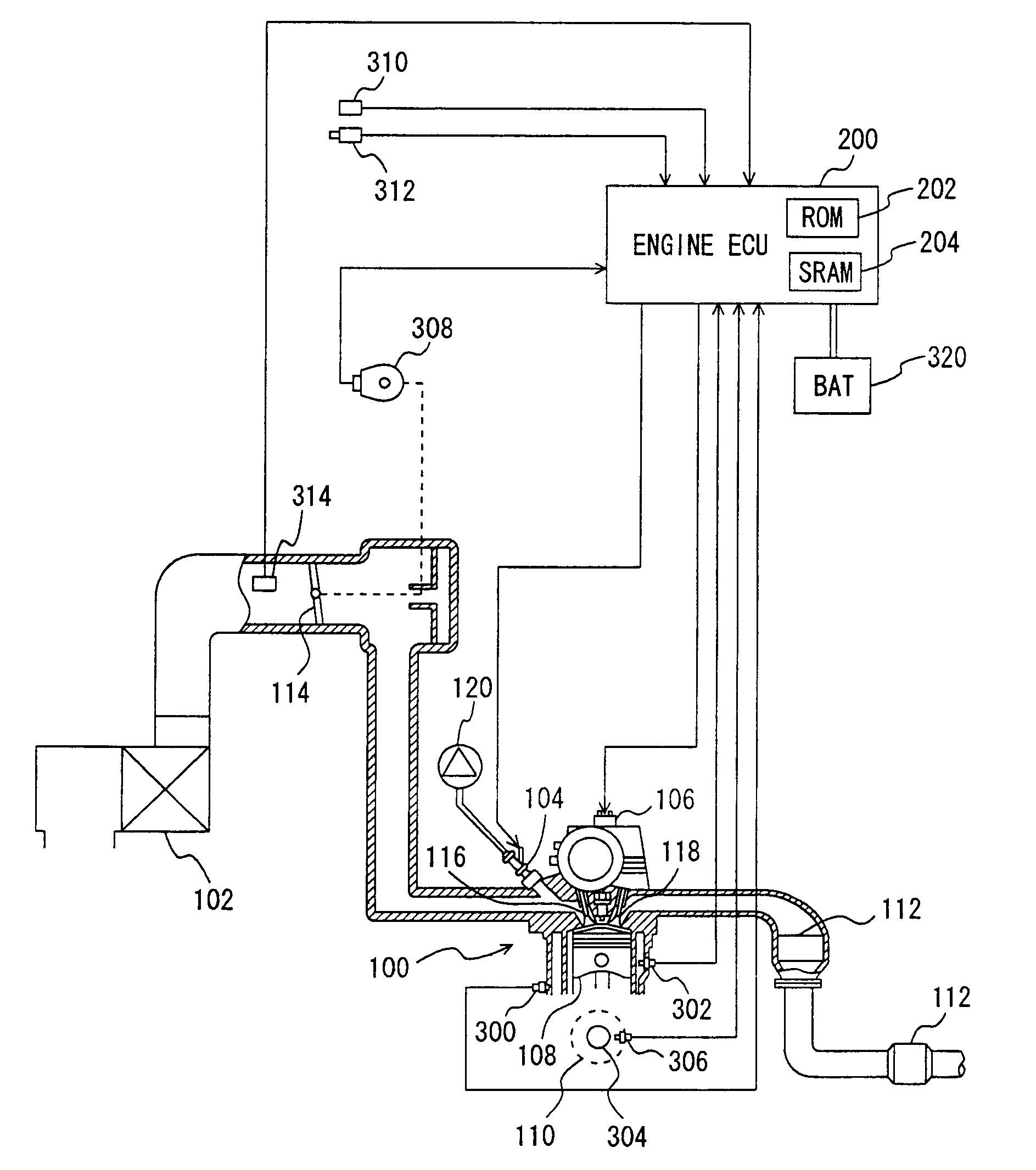
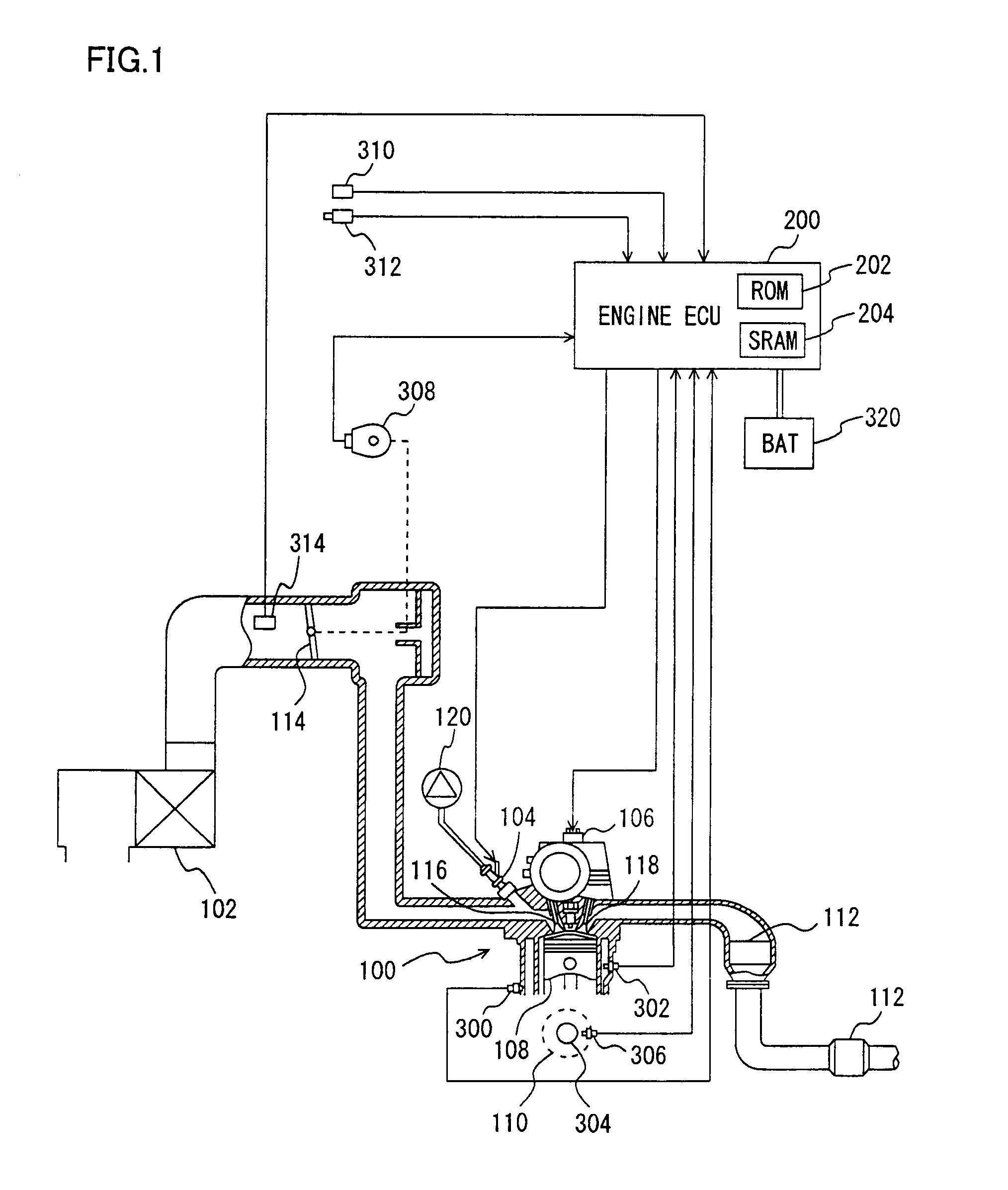
[0030]With reference to FIG. 1, an engine 100 of a vehicle mounted with a device for controlling ignition timing according to the embodiment of the present invention will be described. Engine 100 is provided with a plurality of cylinders. The device for controlling ignition timing according to the present embodiment is accomplished by, for example, a program executed by an engine ECU (Electronic Control Unit) 200.

[0031]Engine 100 is an internal combustion engine in which an air-fuel mixture of air drawn in from an air cleaner 102 and fuel injected from an injector 104 is ignited by a spark plug 106 and burnt in a combustion chamber. Ignition timing is controlled to be MBT (Minimum advance for...


PUM


Abstract

An engine ECU executes a program including a step of calculating a correlation coefficient K representing a degree of agreement between a vibration waveform and a knock waveform model, a step of calculating a knock magnitude N by dividing a peak value P of magnitude in the vibration waveform by BGL, a step of determining whether knocking has occurred based on a combination of the correlation coefficient K and the knock magnitude N, in such a manner as to determine that knocking has not occurred in at least one of the case where the correlation coefficient K is smaller than a threshold value K(1) and the case where the knock magnitude N is smaller than a threshold value N(1), and a step of retarding ignition timing by a retarding amount corresponding to the combination of the correlation coefficient K and the knock magnitude N, if knocking has occurred.

Description

[0001]This nonprovisional application is based on Japanese Patent Application No. 2006-167726 filed with the Japan Patent Office on Jun. 16, 2006, the entire contents of which are hereby incorporated by reference.BACKGROUND OF THE INVENTION[0002]1. Field of the Invention[0003]The present invention relates to a device and a method for controlling ignition timing of an internal combustion engine, and particularly relates to a technique of determining whether knocking is present or absent based on a waveform of vibration and magnitude of vibration of the internal combustion engine and retarding ignition timing in accordance with a determination result.[0004]2. Description of the Background Art[0005]Conventionally, various methods of detecting knocking (knock) generated in an internal combustion engine have been proposed. For example, there is a technique of determining occurrence of knocking if magnitude of vibration of an internal combustion engine is greater than a threshold value. H...

Claims


Application Information

Patent Timeline
IPC IPC(8): F02P5/00
CPCF02D35/027Y02T10/46G01L23/225F02P5/152Y02T10/40
Inventor YOSHIHARA, MASATOMOKASASHIMA, KENJIKANEKO, RIHITOSENDA, KENJITAKEMURA, YUUICHIOE, SHUHEI
Owner TOYOTA JIDOSHA KK
Features
  • R&D
  • Intellectual Property
  • Life Sciences
  • Materials
  • Tech Scout
  • Unparalleled Data Quality
  • Higher Quality Content
  • 60% Fewer Hallucinations
Learn More