
Impact fastener tool with cap feed

Active Publication Date: 2007-12-20
NAT NAIL
View PDF41 Cites 10 Cited by
  • Summary
  • Abstract
  • Description
  • Claims
  • Application Information

AI Technical Summary

Benefits of technology

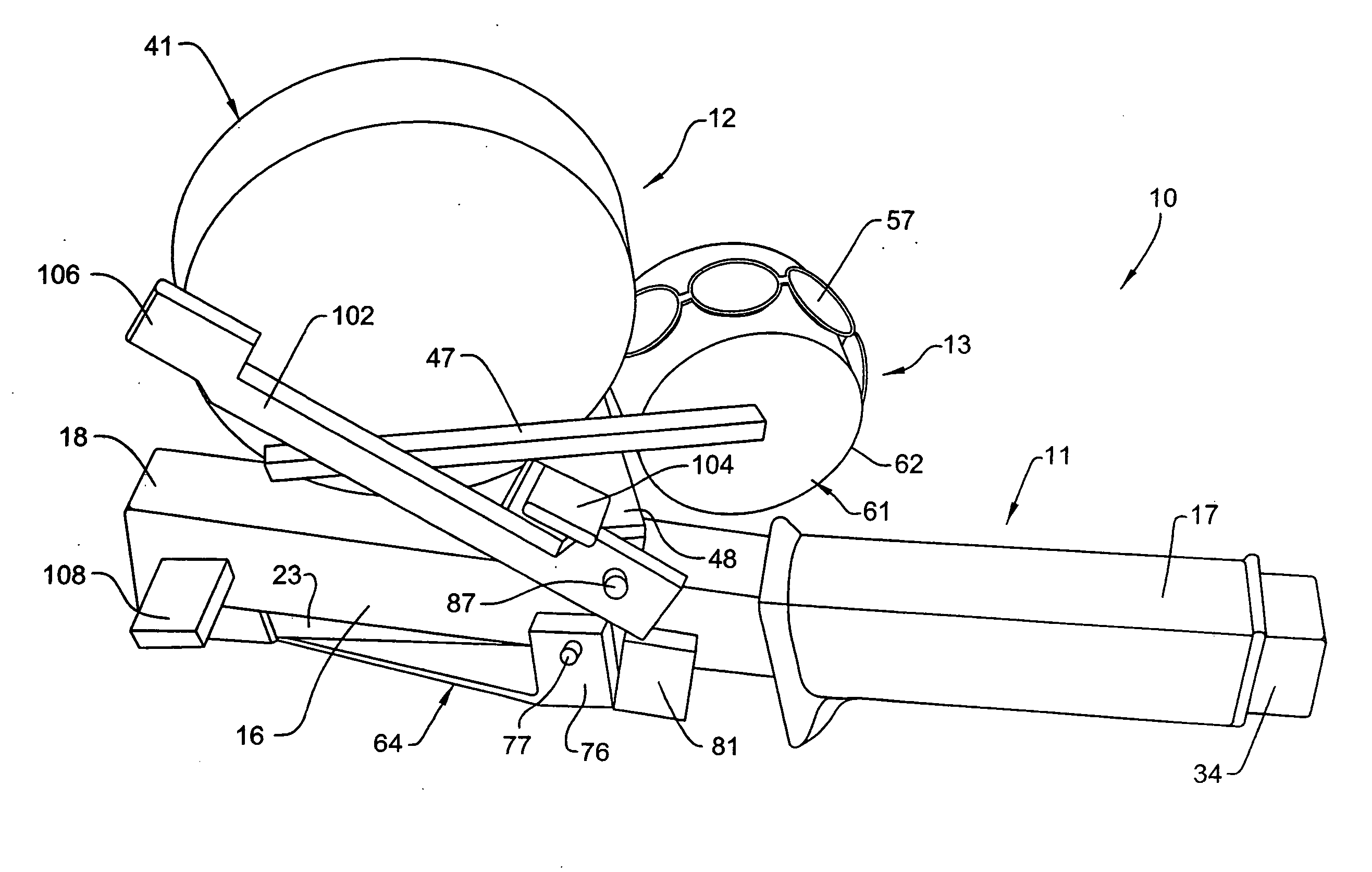
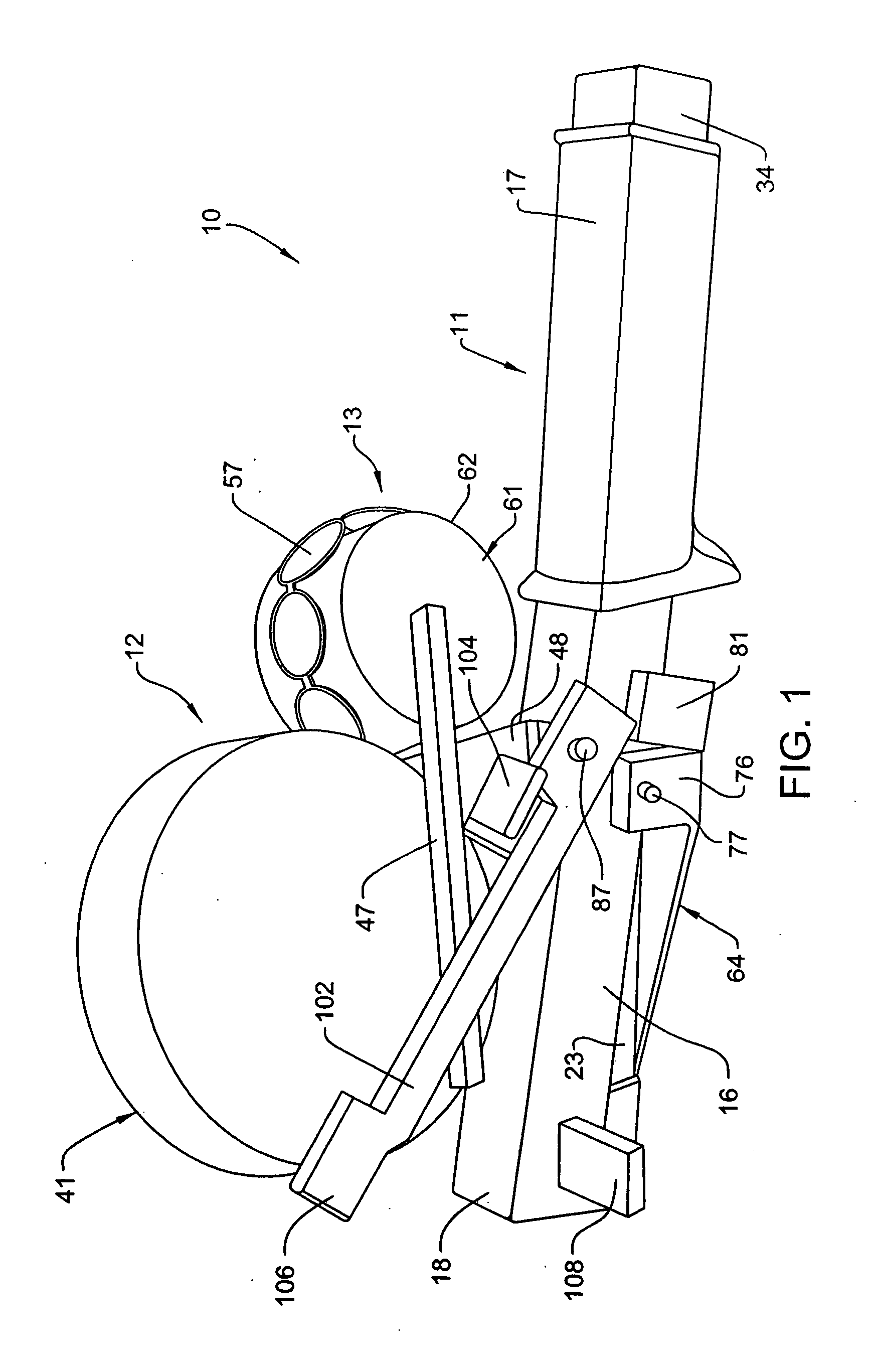
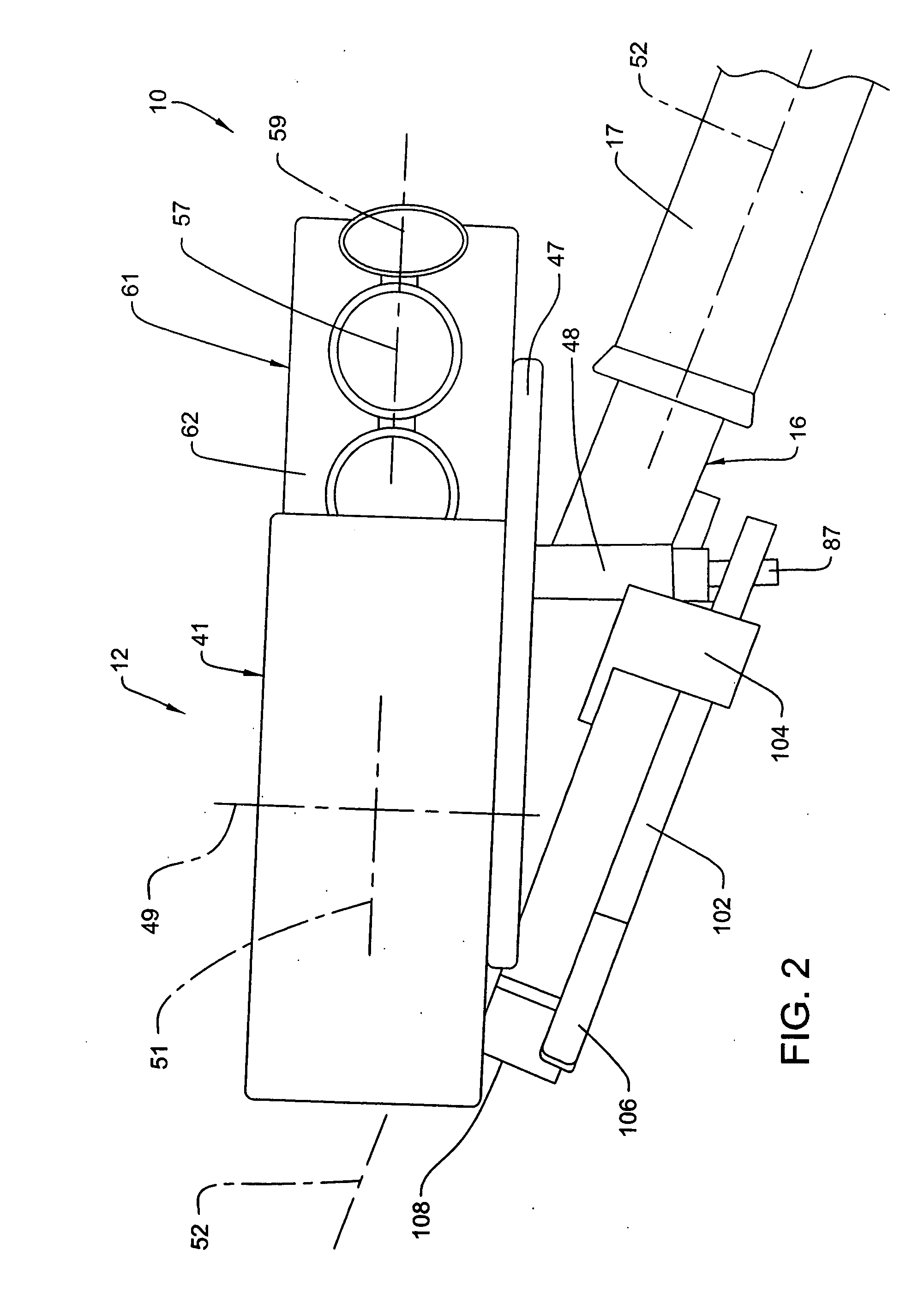
[0012] Still another object of the invention is to provide an improved hammer-type tool, as aforesaid, wherein the cap strip is formed into a spirally-wound spool which is disposed in a cap storage chamber mounted directly on the housing of the tool adjacent one side thereof, and generally between the front and rear ends of the tool, thereby minimizing the overall length of the tool. In addition, the activating mass for activating the cap feeder, and the cap storage canister, are preferably disposed adjacent opposite sides of the tool to provide the tool with desirable side-to-side balance. The actuating mass is also preferably provided in close proximity to the head end of the tool so as to provide maximum efficiency with respect to generation of inertial energy, and the providing of the activating mass and the cap canister in the vicinity of the head end of the tool provides the head end with additional counter-weight effect, and

Problems solved by technology

While tools of this type perform a desirable and efficient stapling operation, nevertheless such tools may be disadvantageous with respect to their cost and their need for connection to a power source, such as a source of pressurized air for operating the tool.
These tools are also generally fairly large and heavy, and the associated air hose makes tools of this type difficult to use when the sheathing or sheet material is being fastened to a relatively upright surface.
In addition, with many of the known tools, such as those illustrated in the U.S. Pat. Nos. 5,184,752 and 6,303,310 patents mentioned above, the tool includes a rather large upright canister for containing therein a vertical stack of caps, all of which are independent of one another, whereby loading of the tool with caps may be difficult, particularly when one considers the environment within which the tools are utilized.
Further, the tool of '389 has the cap supply cylinder positioned forwardly from the impact end of the tool, which may cause overweighing of the head end of the tool and may provide an undesirable balance with respect to the feel of the tool when gripped and manually operated.
Since the tool requires a deliberate manual activating of the cap feeding mechanism, however, such may be considered less effective in job situations where a large volume of impact fastening operations is to be carried out in rapid succession.

Method used


Image

  • Impact fastener tool with cap feed
  • Impact fastener tool with cap feed
  • Impact fastener tool with cap feed

Examples


Embodiment Construction

[0026] Referring to FIGS. 1-7, there is illustrated a preferred embodiment of a manually-operated hammer-type cap fastener tool 10 according to the present invention. This tool 10, in the disclosed and preferred embodiment, uses staples as fasteners, and is defined principally by a stapler unit 11 having a cap supply 12 mounted adjacent the head end of the tool, a guide arrangement 13 for feeding individual caps into a discharge position adjacent the head or impact end of the tool, and a feeding arrangement 14 which effects controlled feeding of caps toward the discharge position.

[0027] The stapler unit 11, considered by itself, is generally conventional and well known, but will be described herein both for background purposes and for facilitating description of its structural and functional cooperation with the cap supply, feeding and discharge features associated with the present invention.

[0028] More specifically, the stapler unit 11 (FIGS. 8 and 9) includes an elongate rigid h...


PUM


Abstract

A manually swingable hammer-type stapling tool having an elongate housing having a striker movably mounted thereon; a staple driving blade mounted on the housing and movable relative to the striker along a staple discharge path when the striker impacts against a surface; a staple magazine carried on said housing and containing a clip of staples so that a leading staple of the clip is disposed in a staple discharge path below the driving blade; and a cap supply and feeding arrangement mounted on the housing for positioning a cap in a discharge position wherein it is disposed below the leading staple, the arrangement including a cap magazine containing a significant number of individual caps disposed in adjacent and joined edge-to-edge relationship to define a connected strip of caps, and an inertia energy activated feeding mechanism for advancing a leading cap of the strip into the discharge position.

Description

CROSS REFERENCE TO RELATED APPLICATION [0001] This application claims the benefit of U.S. Provisional Application No. 60 / 814,182, filed Jun. 16, 2006.FIELD OF THE INVENTION [0002] This invention relates to a hammer-type fastener tool, specifically a stapler tool, and in particular relates to improvements in the constructional and operational features of such tool which permit impact-actuated automatic advancing of a cap strip. BACKGROUND OF THE INVENTION [0003] Heavy duty stapling tools are widely used in the building or construction industry, with such tools being both of the power driven type, typically pneumatic driven tools, and manual type, commonly referred to as hammer-type staplers since the tool is manually swung and impacted against a surface such as a roof or wall substrate so as to effect ejection of a staple. [0004] To permit use of staples for securing sheathing and sheeting to walls and roofs, often as a substitute for a cap nail, tools have been developed which posit...

Claims


Application Information

Patent Timeline
IPC IPC(8): B25C7/00
CPCB25C7/00
Inventor BRUINS, ROGER C.VANDEN BERG, ROGER A.KOOIENGA, ROSS
Owner NAT NAIL
Features
  • Generate Ideas
  • Intellectual Property
  • Life Sciences
  • Materials
  • Tech Scout
  • Unparalleled Data Quality
  • Higher Quality Content
  • 60% Fewer Hallucinations
Learn More