Video encoder/decoder, method and computer program product that process tiles of video data

a video data and encoder technology, applied in the field of video encoders/decoders, methods and computer program products, can solve the problems of reducing placing an even worse burden on the encoder, and unnecessary restrictions on how a frame is processed, so as to maximize the degree of parallel processing flexibility and minimize the penalty on compression efficiency

Active Publication Date: 2012-07-19
CISCO TECH INC
View PDF6 Cites 83 Cited by
  • Summary
  • Abstract
  • Description
  • Claims
  • Application Information

AI Technical Summary

Benefits of technology

[0032]Typically, a video decoder specification defines sequential block processing in raster scan order as the normal mode of operation. This ensures maximum compression efficiency by allowing dependency between neighbour blocks of the same frame to be exploited without restrictions. Typically, this implies that parameters for a given block depend on the same parameters in the blocks to the left and above. As described previously, this typically applies to reconstructed pixels for intra prediction, motion vector coding, intra direction mode coding, and adaptive entropy coding.
[0034]Preferably, according to the present invention the cores have access to shared memory where the previous reconstructed frames are stored. In those cases, dependencies between neighbouring blocks only needs to be broken for the current frame, allowing for unrestricted choice of motion vectors.
[0035]Accordingly, one aspect of the present invention is it minimizes the penalty on compression efficiency, while maximizing the degree and flexibility of parallel processing when encoding video frames.

Problems solved by technology

Having to decode a bit stream that uses raster-scan order within a slice-group is a highly undesirable requirement for many decoders, especially those using a single core.
Having to decode e.g. all the “white” blocks before all the “black” blocks of a checkerboard pattern or even more sophisticated patterns place an even worse burden on a decoder.
In turn, this imposes an unnecessary an often undesired restriction on how a frame can be divided into independently decodable blocks.
Even though the definition of slice groups gives the encoder flexibility to define almost any partition of the frame, the scheme has some undesired implications on the decoder.
This might have severe implications on the decoder implementation as the decoder must be designed to handle almost arbitrary scan-orders.
Another disadvantage of the slice groups in AVC / H.264 is that a maximum of 8 slice groups are allowed, and that each slice group consist of a separate slice including a slice header.

Method used


Image

  • Video encoder/decoder, method and computer program product that process tiles of video data
  • Video encoder/decoder, method and computer program product that process tiles of video data
  • Video encoder/decoder, method and computer program product that process tiles of video data

Examples


Embodiment Construction

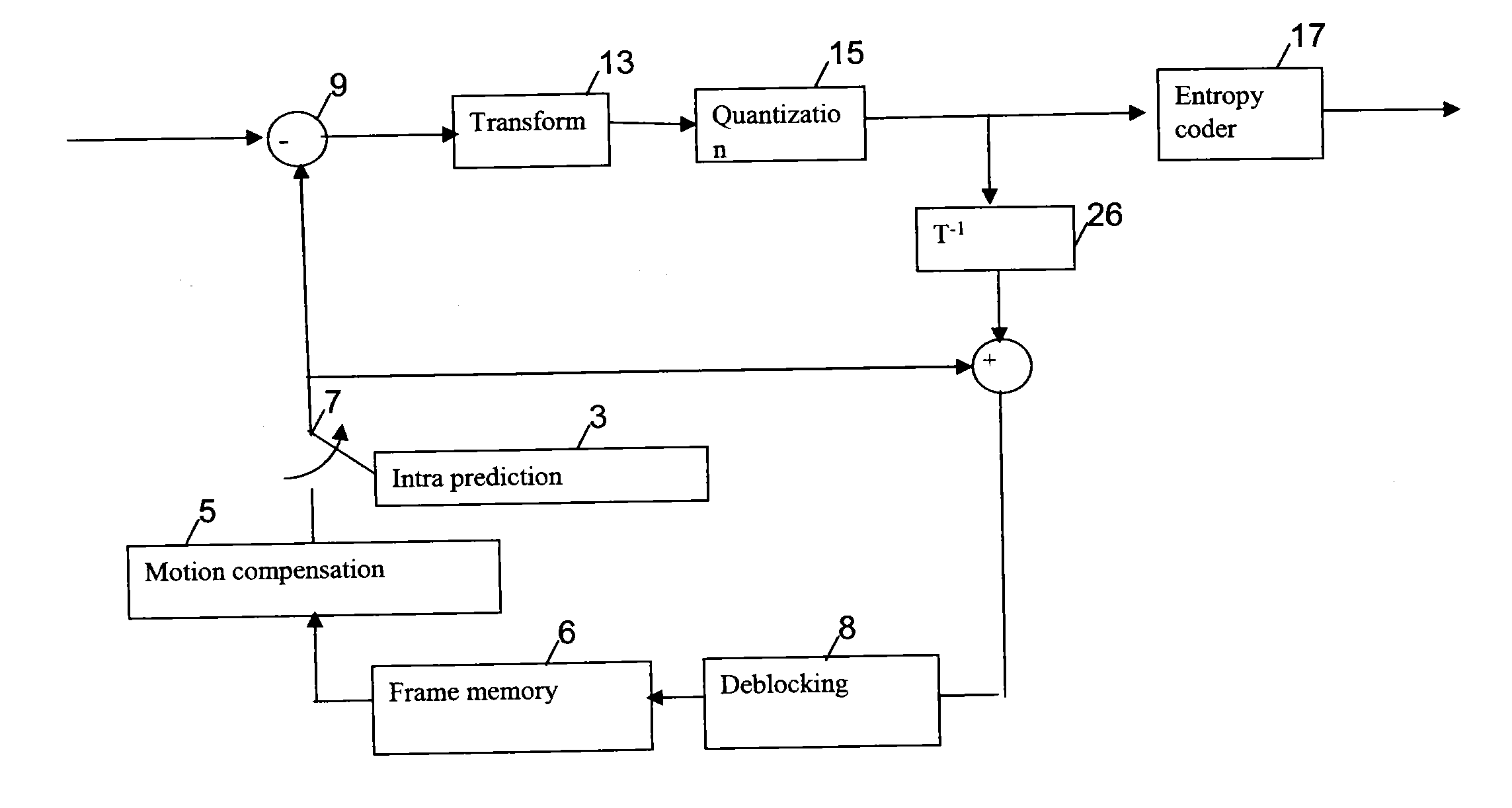
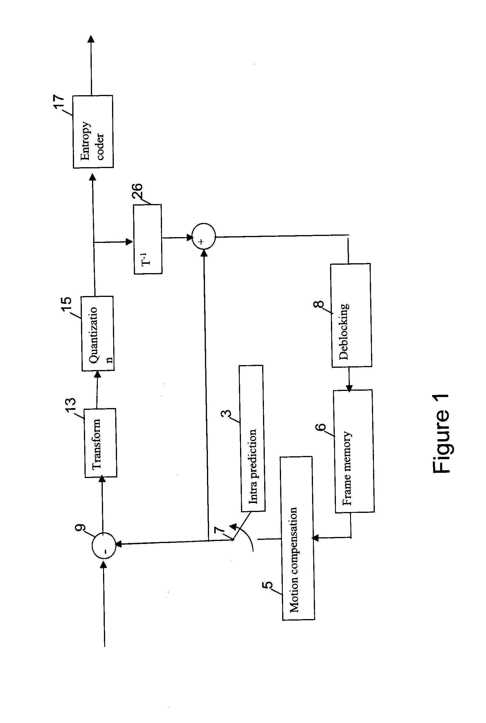
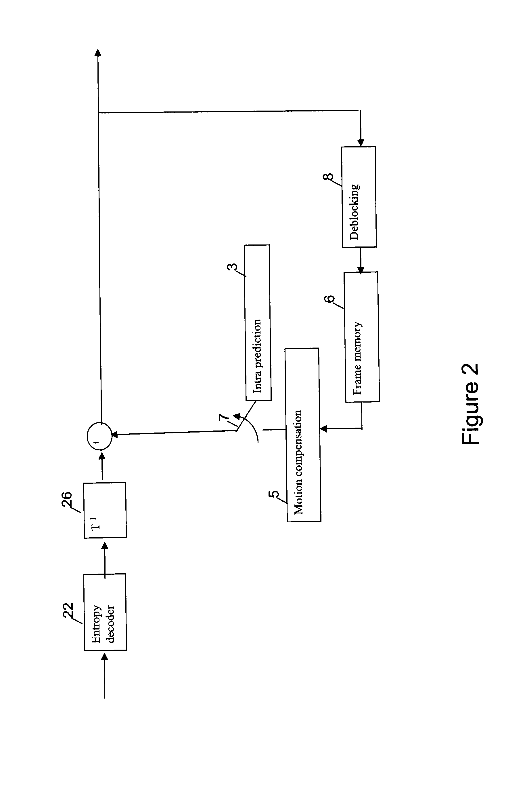
[0045]The present embodiment introduces the notion of “tiles” to exploit the two dimensional dependencies between blocks while also supporting the exploitation of multiple processors, if available in the encoder, to simultaneously perform encoding operations on multiple tiles. The partitioning of a frame into tiles is completely specified by the numbers N and M, eliminating the need for a slice header, which is a basic requirement in conventional slice processing. Here, N and M are the height and width of a tile measured in number of blocks. Typically, the values of N and M are conveyed to the decoder in the sequence header or picture header resulting in negligible transmission bandwidth overhead. In addition to unilaterally transmitting the N and M numbers to the decoder in the sequence or picture header, an alternative is to have a handshaking operation between the decoding device and encoding device, where the values of N and M are exchanged, as well as perhaps the processing cap...


PUM


Abstract

In video encoding it is common to encode the image data to remove redundancies in the information to be transmitted. While the pixel data is usually arranged in pixel blocks, the blocks can be arranged in one or more groups of N×M blocks called tiles. The tiles avoid the need to send header information on a tile-by-tile or block-by-block basis, and simplifies parallel processing of the tiles. Bits from respective tiles may then be reformatted to recreate bits according to a raster-scan direction. This enables the decoder to receive the bits in a regular raster-scan format, but also have the ability to decode the tiles once the bits are reformatted. By partitioning an image into tiles of size N×M, it is possible to further exploit the intra-frame correspondence of images in a vertical direction as well as horizontal direction since the tiles need not destroy as many dependencies between blocks in a tile as if the blocks where organized in slices or slice groups.

Description

BACKGROUND[0001]1. Field of the Disclosure[0002]The present application relates to video encoders / decoders, methods and computer program product generally, and more particular to video encoders / decoders, methods and computer program product that process groups of adjacent blocks arranged in tiles.[0003]2. Description of the Related Art[0004]The “background” description provided herein is for the purpose of generally presenting the context of the disclosure. Work of the presently named inventor, to the extent it is described in this background section, as well as aspects of the description which may not otherwise qualify as prior art at the time of filing, are neither expressly or impliedly admitted as prior art against the present invention.[0005]A video encoder is typically implemented by dividing each frame of original video data in blocks of pixels. In existing standards for video compression (e.g., MPEG1, MPEG2, H.261, H.263, and H.264) these blocks would normally be of sized 16...

Claims


Application Information

Patent Timeline
Patent Type & Authority Applications(United States)
IPC IPC(8): H04N7/26
CPCH04N19/119H04N19/61H04N19/436H04N19/174H04N19/156
Inventor FULDSETH, ARILD
Owner CISCO TECH INC
Why Eureka
Try Eureka