Tube Pump, Ink Jet Recording Device, and Ink Feeding Method

Inactive Publication Date: 2007-12-27
SII PRINTEK +1
View PDF2 Cites 33 Cited by
  • Summary
  • Abstract
  • Description
  • Claims
  • Application Information

AI Technical Summary

Benefits of technology

[0011] A tube pump according to the present invention includes: a pump main body having a space portion defined therein, including: a circular arc-shaped guiding member formed on an inner circumference of the pump main body over a predetermined angle range; and an opening portion communicating with the space portion; a tube provided along the guiding member and led out from the opening portion; at least one pressing member rotationally driven around a shaft coaxial with the guiding member, for pressing the tube against the guiding member; driving means for controlling the rotational drive; and flow passage securing means provided to the guiding member to which the tube is provided. Accordingly, when the pump is stopped for replacing a main tank, negative pressure inside an ink supply passage and the main tank can be eliminated.
[0012] Further, in the tube pump of the present invention, the flow passage securing means is defined by at least one recessed portion of the guiding member, in which the tube is not pressed by the guiding member and the pressing member. Accordingly, during stoppage for replacing the main tank, the negative pressure inside the main tank can be eliminated with a simple mechanism and operation.
[0013] Further, in the tube pump of the present invention, the number of the pressing member is the same as the number of the recessed portion or larger than the number of the recessed portion by one. Accordingly, it is possible to reliably prevent air from entering the ink supply passage from atmosphere and to sufficiently exert pump efficiency required for supplying the ink.
[0014] Further, an ink jet recording device according to the present invention is an ink jet recording device for performing recording onto a recording medium by jetting ink from recording means, which includes a tube pump including: a pump main body having a space portion

Problems solved by technology

Therefore, in a case where air bubbles are included in the ink, the pressurized state of the ink becomes unstable and jet performance of the ink droplets is lowered, thereby deteriorating a printing quality.
However, the ma

Method used


Image

  • Tube Pump, Ink Jet Recording Device, and Ink Feeding Method
  • Tube Pump, Ink Jet Recording Device, and Ink Feeding Method
  • Tube Pump, Ink Jet Recording Device, and Ink Feeding Method

Examples


Example

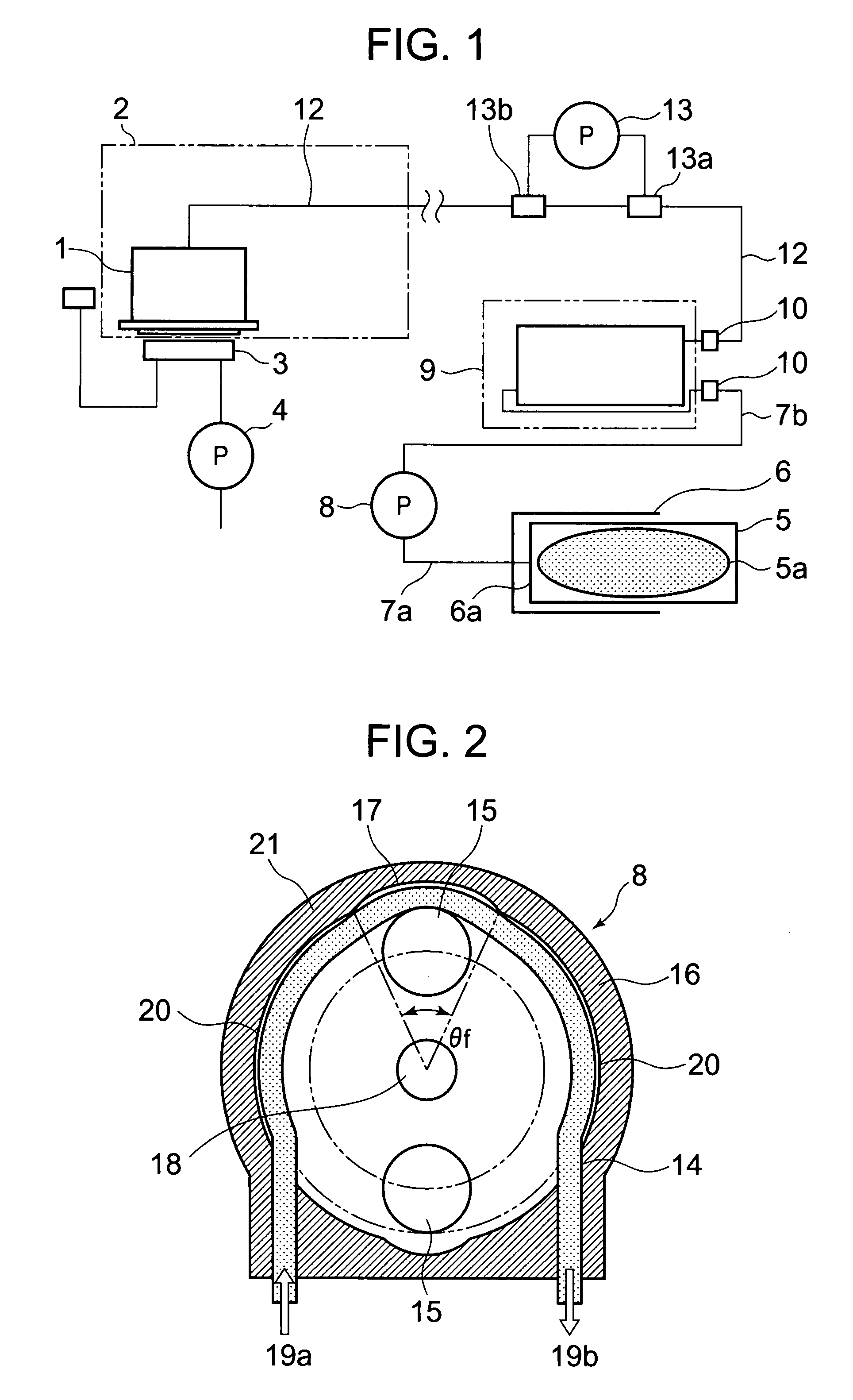
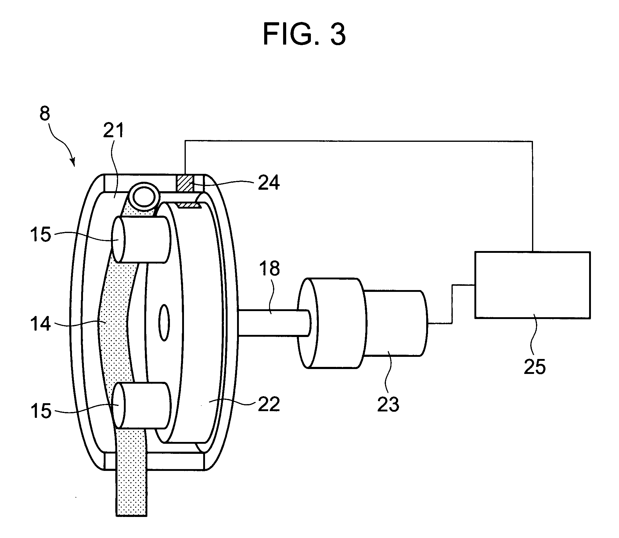
[0031]FIG. 2 is a sectional diagram schematically showing a first embodiment of the tube pump 8 of the present invention for sucking ink in the main tank 5 to the sub-tank 9. Further, FIG. 3 is a diagram showing a control structure of the tube pump of the present invention. The tube pump of the present invention includes a pump main body 21 having a space portion defined therein, which includes a circular arc-shaped guiding member formed on an inner circumference of the pump main body 21 over a predetermined angle range and an opening portion that communicates with the space portion. Inside the space portion, there are arranged an elastic tube 14, a guiding member 16 which is a part of the pump main body, for guiding the tube 14 along the inner circumference, and rollers 15 serving as pressing members for pressing the tube 14 against the guiding member 16.

[0032] In the suction pump 8 of this embodiment, the above-mentioned predetermined angle is 180° or more, and the tube 14 is pro...


PUM


Abstract

A tube pump includes: an elastic tube (14); a circular arc-shaped guiding member (16) for guiding the tube (14); and at least one pressing member (15) for pressing the tube (14) against the guide member (16). The tube pump is characterized by being provided with a recessed portion (17) in a portion of the guiding member (16), in which the tube (14) is not pressurized by the pressing member (15) and can be recessed. Thus, there can be provided a tube pump in which a negative pressure inside an ink supply passage (7) can be eliminated and air can be readily prevented from entering the ink supply passage (7) when the main tank (5) is replaced, and an ink jet recording device using the tube pump.

Description

TECHNICAL FIELD [0001] The present invention relates to a tube pump, and more particularly to a tube pump of an ink jet recording device for jetting ink droplets from a recording head to record an image onto a recording medium, which is used for supplying ink from a main tank serving as an ink supplying source to a sub-tank. BACKGROUND ART [0002] An ink jet recording device of a serial printing system as shown in FIG. 1 includes at least a delivery means for delivering a recording medium in a sub-scanning direction (not shown) and a recording head 1 which is mounted onto a carriage 2 and reciprocates in a main scanning direction orthogonal to the sub-scanning direction. The ink jet recording device has a structure for jetting ink droplets from the recording head 1 at a desired timing according to print data, and allowing the ink droplets to land on a surface of the recording medium, to thereby perform image formation. [0003] In particular, a large ink jet recording device for formin...

Claims


Application Information

Patent Timeline
IPC IPC(8): B41J2/195F04B49/00
CPCF04B43/1253B41J2/17596B41J2/19
Inventor KUBOTA, YUZURUIWASE, FUMIYOSHI
Owner SII PRINTEK
Why Eureka
Try Eureka