

Vane Pump
- Summary
- Abstract
- Description
- Claims
- Application Information
AI Technical Summary
Benefits of technology
Problems solved by technology
Method used
Image

Examples
first embodiment
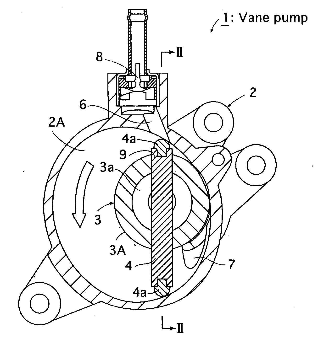
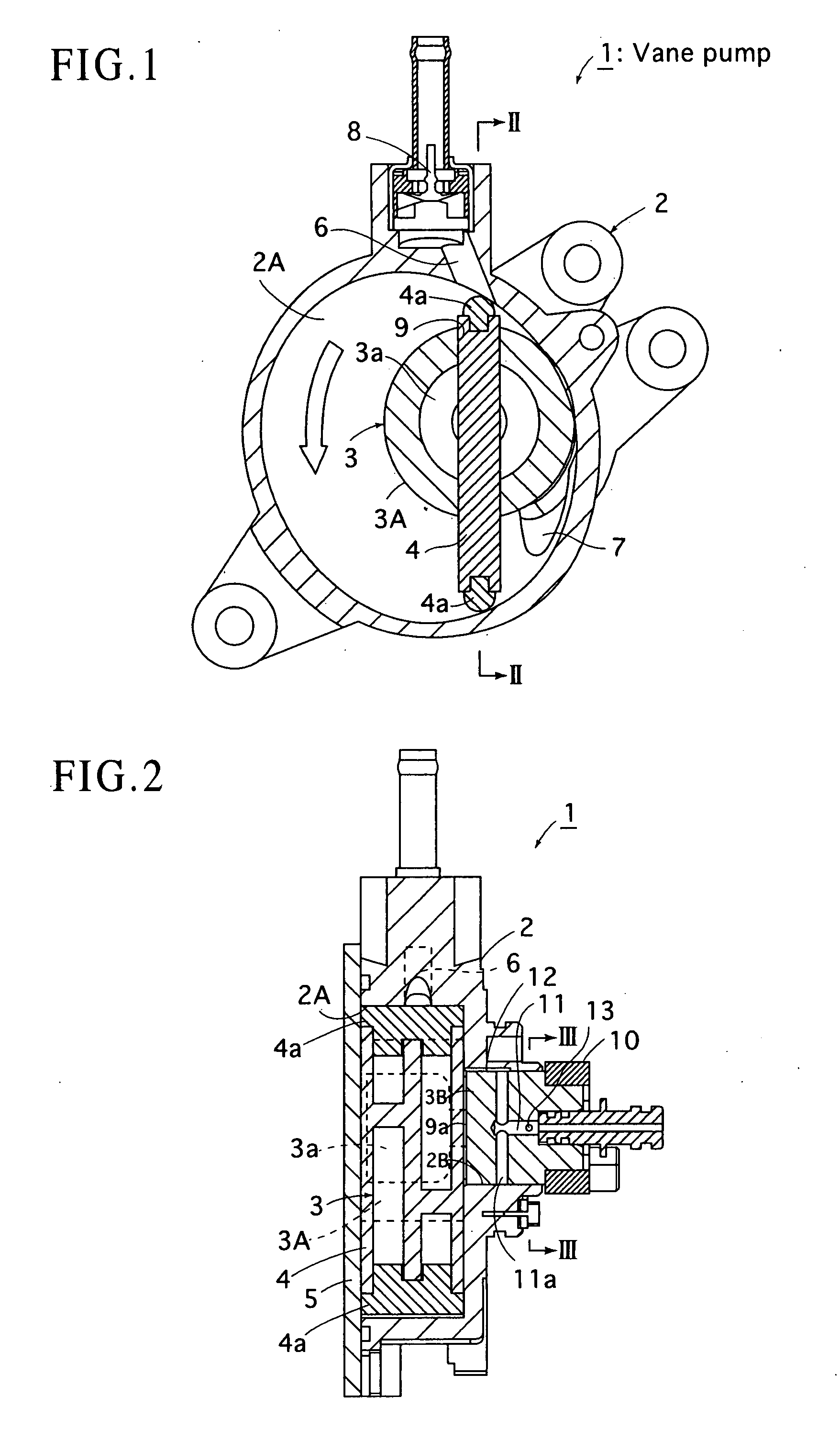
[0018] Now, embodiments shown in drawings will be hereinafter described. FIGS. 1, 2 show a vane pump 1 of a first embodiment according to the present invention. This vane pump 1 is fixed on the side surface of an engine in an automobile not shown, and is configured to generate a negative pressure in a booster of a brake control system not shown.
[0019] This vane pump 1 includes: a housing 2 having an approximately circular pump room 2A formed thereon; a rotor 3 which is rotated at an eccentric position relative to the center of the pump room 2A by a driving force of the engine; a vane 4 rotated by the rotor 3 and for dividing the pump room 2A full-time into a plurality of spaces; and a cover 5 for covering the pump room 2A.
[0020] In the housing 2, an intake passage 6 located above the pump room 2A, in communication with the booster of the brake control system and for sucking in a gas from the booster is provided, and an exhaust passage 7 located below the pump room 2A, for dischargi...
second embodiment
[0076]FIG. 5 is a cross-sectional view of a vane pump of a
PUM
 Abstract
Description
Claims
Application Information