One-time flare mechanism

a one-time flare and mechanism technology, applied in emergency apparatus, parachutes, transportation and packaging, etc., can solve the problems of increasing the size, weight, cost and complexity of the system, and achieve the effect of extending the minimum of the riser control lin

Active Publication Date: 2022-09-06
EARTHLY DYNAMICS LLC
View PDF19 Cites 0 Cited by
  • Summary
  • Abstract
  • Description
  • Claims
  • Application Information

AI Technical Summary

Benefits of technology

[0012]In another embodiment, the one-time flare mechanism comprises an internal pulley mechanism located within the spreader. The internal pulley comprises a single pulley with two grooves, an upper groove and lower groove, with different radii. In this embodiment, the upper groove is smaller in radius than the lower groove. The trailing edge control line is threaded through the spreader to an idler pulley and then is threaded on to the lower groove. In this embodiment each canopy riser is attached to a riser control line that is threaded into the spreader and attached to the upper groove. The release mechanism system of this embodiment comprises a release mechanism and a control mechanism that collectively prevent the movement of the internal pulley until the release mechanism is released. In a preferred embodiment, the release mechanism is a pin and the control mechanism is an aperture that holds the pin in place, but it is understood that any acceptable device for preventing movement of the internal pulley may be used. In a preferred embodiment, the trailing edge control line is secured to the lower groove at the location of the control mechanism. However, it is understood that the release mechanism and control mechanism may be placed at any location and that the trailing edge control line may be secured at any acceptable location on the lower groove. Prior to flight, the riser control lines are pre-wound around the internal pulley. The pulley is then locked in place by the release mechanism. When the release mechanism is activated, the internal pulley rotates to release the pre-wound riser control lines and simultaneously pulls in the trailing edge control line. The smaller groove allows for minimal extension of the riser control lines while creating a significant change in the trailing edge control line causing brake deflection.

Problems solved by technology

Direct control of the trailing edge lines requires actuators capable of producing large control forces, adding to the size, weight, cost and complexity of the system.

Method used


Image

  • One-time flare mechanism
  • One-time flare mechanism
  • One-time flare mechanism

Examples


Embodiment Construction

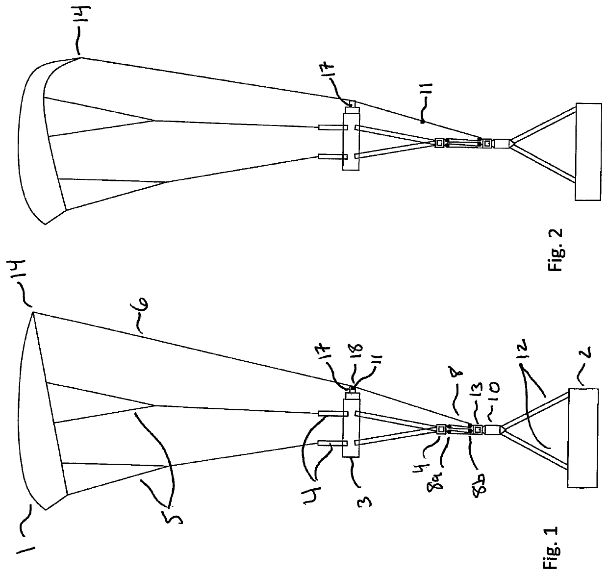
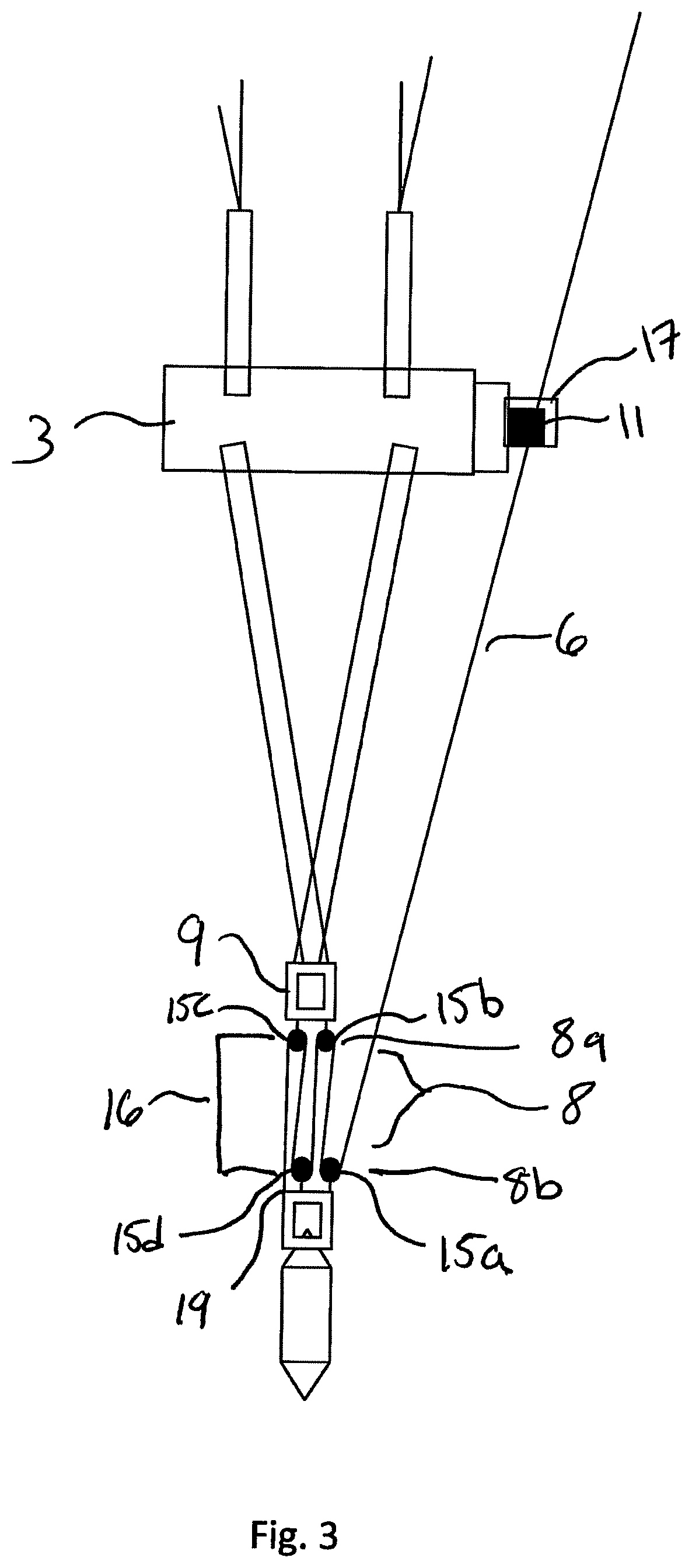
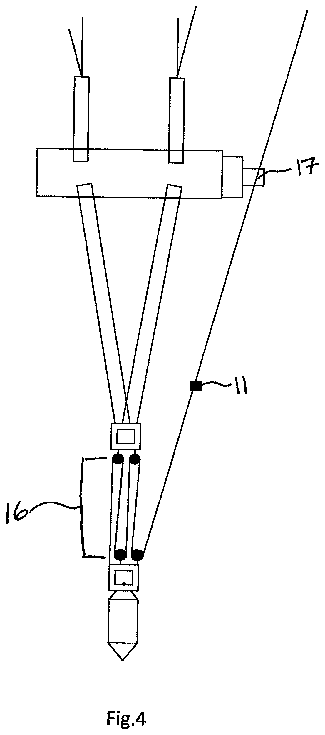
[0022]FIG. 1 is a schematic representation of an embodiment of the present invention with a parafoil canopy 1 attached to suspension lines 5 and trailing edge control line 6. Trailing edge control line 6 is attached to the trailing edge 14 of canopy 1. The suspension lines 5 are further attached to risers 4. Risers 4 are attached to spreader 3. Release mechanism system 18 is connected or associated with spreader 3. Release mechanism system 18 further comprises release mechanism 17 and control line mechanism 11. Control line mechanism 11 is held in place on trailing edge control line 6 by release mechanism 17. The spreader 3 is further attached to upper payload slings 7. Upper payload slings 7 are further attached to upper link 9. Upper link 9 is connected or associated with purchase system 8. Purchase system 8 further comprises an upper purchase system 8a connected or associated with upper link 9 and a lower purchase system 8b connected or associated with lower link 13. Upper purcha...


PUM


Abstract

A one-time flare mechanism system for use with an aerial payload system is describe which uses minimal actuation force to produce a reliable flare with minimal shock to the payload, parafoil and rigging.

Description

STATEMENT OF GOVERNMENT INTEREST[0001]The work that lead to certain aspects of this invention was supported in part by the U.S. Army Natick Soldier Research, Development and Engineering Center. Thus, the United States Government may have certain rights to this invention.CROSS-REFERENCE TO RELATED APPLICATION[0002]The present application is a Continuation-In-Part Application claiming benefit of U.S. application Ser. No. 14 / 923,619 filed Oct. 27, 2015. The subject matter of that application is hereby incorporated by reference in its entirety.FIELD OF THE INVENTION[0003]The present invention relates to a mechanism to produce a one-time flare in a reliable manner with minimal shock loads for an aerial payload delivery system.BACKGROUND OF THE INVENTION[0004]Aerial payload delivery systems offer the capability to deliver large payloads and or people to undeveloped or inaccessible locations. The canopies in these systems are well known and often referred to as parafoils from which payload...

Claims


Application Information

Patent Timeline
Patent Type & Authority Patents(United States)
IPC IPC(8): B64D17/34B64D17/38
CPCB64D17/34B64D17/38B64D1/14
Inventor COSTELLO, MARK FWARD, MICHAEL BRIAN
Owner EARTHLY DYNAMICS LLC
Why Eureka
Try Eureka