Movable-contact unit and panel switch using the same

a technology of moving contact and panel switch, which is applied in the direction of contact surface shape/structure, emergency protective device, thin material handling, etc., can solve the problems of degraded tactile feedback and high rigidity of low temperature environment, and achieve adequate tactile feedback and adequate tactile feedback

Inactive Publication Date: 2008-01-10
PANASONIC CORP
View PDF10 Cites 3 Cited by
  • Summary
  • Abstract
  • Description
  • Claims
  • Application Information

AI Technical Summary

Benefits of technology

[0017]The present invention addresses the problem discussed above, and aims to provide a movable-contact unit formed of an inorganic EL sheet which holds movable contacts directly, and the movable-contact unit allows providing the user with adequate tactile feedback even in a low temperature environment. The present invention also aims to provide a panel switch employing the foregoing movable-contact unit.
[0018]The movable-contact unit of the present invention is formed of an EL sheet, and domed movable contacts made of thin metal sheet and held adhesively on the underside of the EL sheet at their top faces via adhesive. The adhesively held status of the unit by the EL sheet can be set such that the movable-contact unit can provide the user with adequate tactile feedback even in a low temperature environment. To be more specific, the adhesive used for holding the movable contacts has an area of 25-50% of the area of each one of the movable contacts, and the adhesive is patterned within the foregoing area ratio for holding each one of the movable contacts. The foregoing area ratio allows the movable contacts to provide the user with tactile feedback almost free from degradation even in the low temperature environment.

Problems solved by technology

The movable-contacts unit under study employs inorganic EL sheet 40; however, EL sheet 40 has some problem, i.e. it is thicker than conventional base sheet 1 because of multi-layer printings, and yet, it becomes highly rigid in a low temperature environment.
The inventors thus encounter the problem that the operation in the low temperature environment provides the user with degraded tactile feedback obtained from movable contacts 5.

Method used


Image

  • Movable-contact unit and panel switch using the same
  • Movable-contact unit and panel switch using the same
  • Movable-contact unit and panel switch using the same

Examples


Embodiment Construction

[0028]An exemplary embodiment of the present invention is demonstrated hereinafter with reference to FIG. 1-FIG. 5, and similar elements to those used in the conventional model have the same reference marks and the descriptions thereof are omitted here.

Exemplary Embodiment

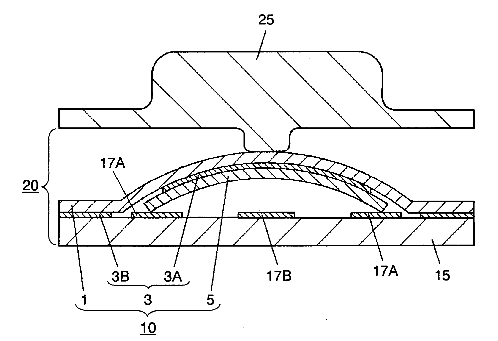
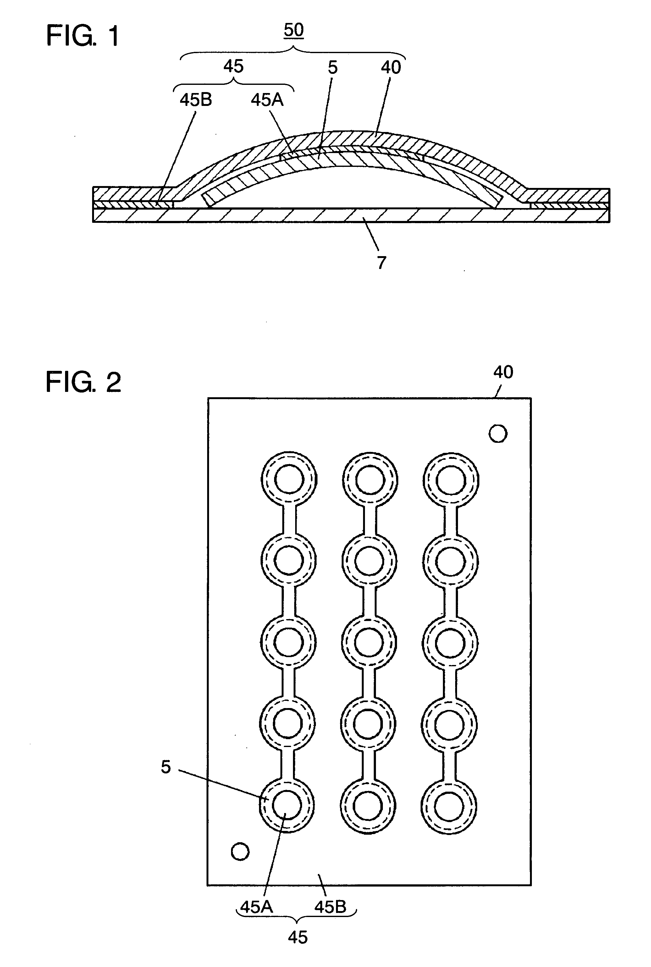
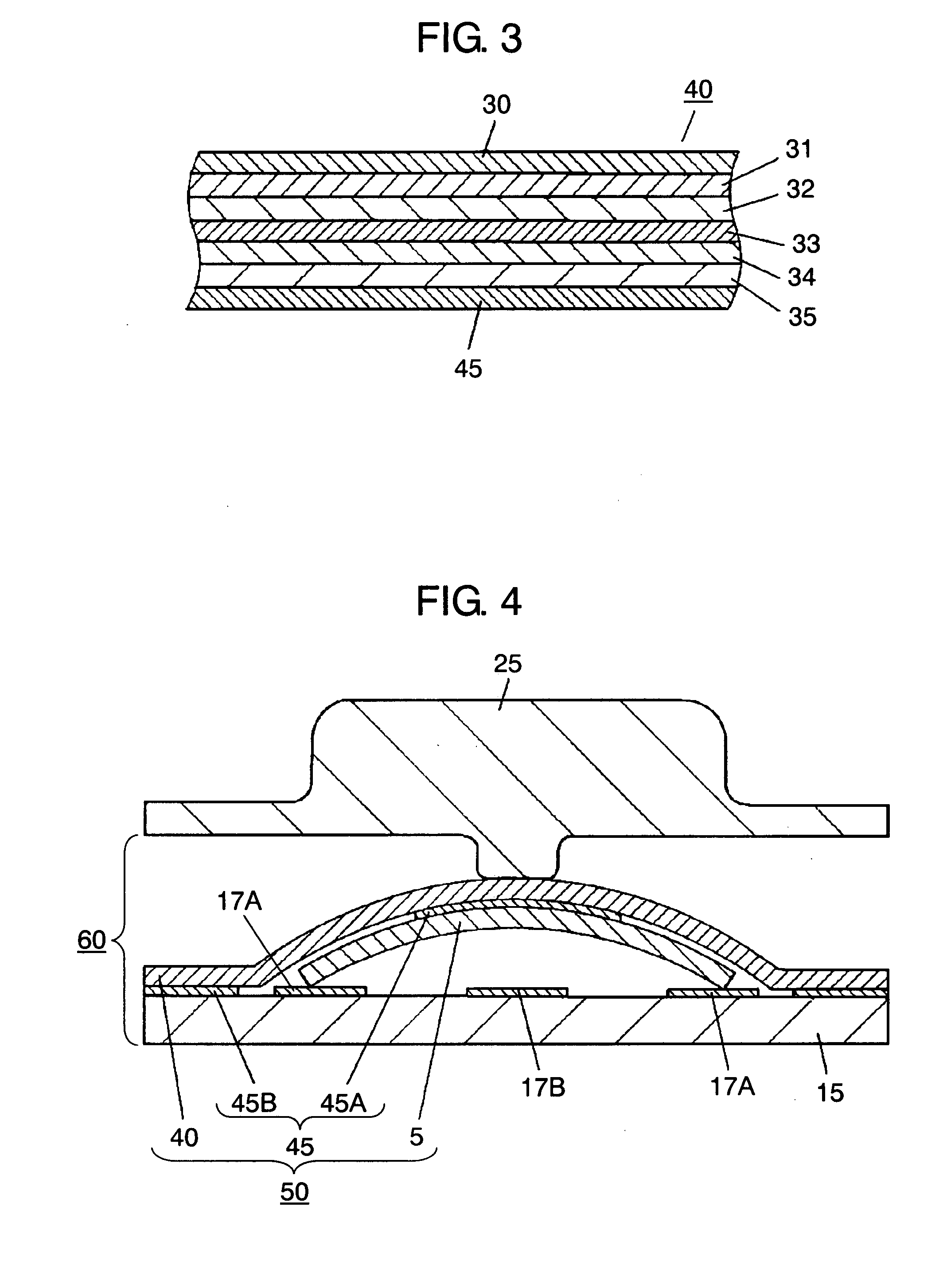
[0029]FIG. 1 shows a sectional view of a movable-contact unit in accordance with the embodiment of the present invention. FIG. 2 shows a bottom view illustrating the adhesive patterned on an inorganic EL sheet, an essential part of the movable-contact unit. FIG. 3 shows a sectional view illustrating the adhesive printed on the inorganic EL sheet, an essential part of the movable-contact unit. As shown in FIG. 1, movable-contact unit 50 is formed this way: acrylic adhesive 45 is printed on inorganic EL sheet 40 per se, then movable contacts 5 are bonded to EL sheet 40 via adhesive 45.

[0030]Adhesive 45 is the same adhesive used in the conventional unit, and the formed pattern of adhesive 45 is a critical point of the...


PUM


Abstract

A movable-contact unit to be used in an operating panel of various electronic devices is disclosed. The movable-contact unit is formed of movable contacts directly held on an inorganic EL sheet. To obtain adequate tactile feedback from the movable contacts even in a low temperature environment, a holding section of adhesive is patterned on the underside of the inorganic EL sheet such that the area of the holding section is not less than 25% and not greater than 50% of the area of the movable contact. Then the movable contact is held adhesively by this patterned holding section of the adhesive.

Description

FIELD OF THE INVENTION[0001]The present invention relates to a movable-contact unit to be used in an operating panel of various electronic devices, and it also relates to panel switches using the same movable-contact units.BACKGROUND OF THE INVENTION[0002]A variety of electronic devices have also various structures in their inputting sections. Portable devices, among other electronic devices and typically represented by portable phones, have increasingly used a panel switch as an operating panel. The panel switch is formed by placing a movable-contact unit on a printed wired board of an electronic device, and the movable-contact unit is formed by adhesively holding movable contacts on the underside of a base sheet made of insulating film such as PET.[0003]Due to their portability, the portable devices can be used in various environments including a wide range of temperature, so that the operating panel needs to be operated smoothly in the various environments. The foregoing conventi...

Claims


Application Information

Patent Timeline
Patent Type & Authority Applications(United States)
IPC IPC(8): B65H3/20
CPCH01H13/83H01H13/85H01H2239/072H01H2219/018H01H2215/004
Inventor NISHIMURA, TAKAHIRO
Owner PANASONIC CORP
Why Eureka
Try Eureka