Optical symbol scanner and illuminator with powered socket

a technology of optical symbols and powered sockets, applied in the field of optical scanning devices, can solve the problems of inability to carry an operator, inability to read bar codes in warehouses, shipping docks or receiving docks, and the bulky and non-portable scanner systems, and achieve the effect of reducing or eliminating the emission of black ligh

Active Publication Date: 2008-01-10
INDAL DATA ENTRY AUTOMATION SYST
View PDF10 Cites 34 Cited by
  • Summary
  • Abstract
  • Description
  • Claims
  • Application Information

AI Technical Summary

Benefits of technology

[0017]In some preferred embodiments, the illuminator module can include a shroud, with the optical passageway thereof having its optic axis aligned with the optic axis of said scanning device. In the case of an illumination attachment for luminescent targets or symbols, the LEDs or other illumination generating means in the module can incorporate one or more diodes that generate a predetermined black light wavelength appropriate for the luminescent targets or symbols. The luminescent materials of those symbols respond and emit light of another wavelength. In this case, the shroud has a channel within it for directing and guiding the stimulating illumination, e.g., black light. A narrow distal end of the shroud may have an optional flat plate that is transparent to radiation at the black light wavelength and the other wavelength. The shroud can favorably be formed with a tapered opaque shell that narrows in the direction towards the distal end, such that the radiation at said black light wavelength impinges on the symbol and the scanner device views the symbol as radiation at the other wavelength as produced by said fluorescent markings. Stray emission of the black light is reduced or eliminated, and the viewing parts of the scanning device are also shielded from much of the ambient light. The plate of transparent material at the narrow distal end can be oriented at a non-right angle to said optic axis such that the light that hits the plate is not reflected directly back to the imager device.

Problems solved by technology

These scanner systems are bulky and non-portable, so they cannot be carried by an operator.
This makes it impossible to read the bar codes in a warehouse, shipping dock or receiving dock environment where the workers could be provided with hand-held scanners.
In addition, because of the rather harmful effects from ultraviolet radiation, conventional black light sources typically have to be shielded to protect the workers from exposure to skin or eyes.
Consequently, invisibly printed fluorescing bar code symbols can only be read under special circumstances, as the bulk, weight, and complexity of the reader equipment has limited their widespread usage.
No one previously had considered using black-light emitting diodes in connection with any sort of hand-held scanner device to permit their use in reading “invisible” luminescent or fluorescent optical symbols, such as bar codes.
However, prior hand held scanners are unable to discern bar coded symbols formed of these fluorescent inks, because of the low contrast between the target and background.
Also, some bar code symbols are embossed, etched, or peened onto a smooth reflective surface and these symbols have been difficult or impossible to read, unless a special illuminator is in place on the scanner.

Method used


Image

  • Optical symbol scanner and illuminator with powered socket
  • Optical symbol scanner and illuminator with powered socket
  • Optical symbol scanner and illuminator with powered socket

Examples


Embodiment Construction

)

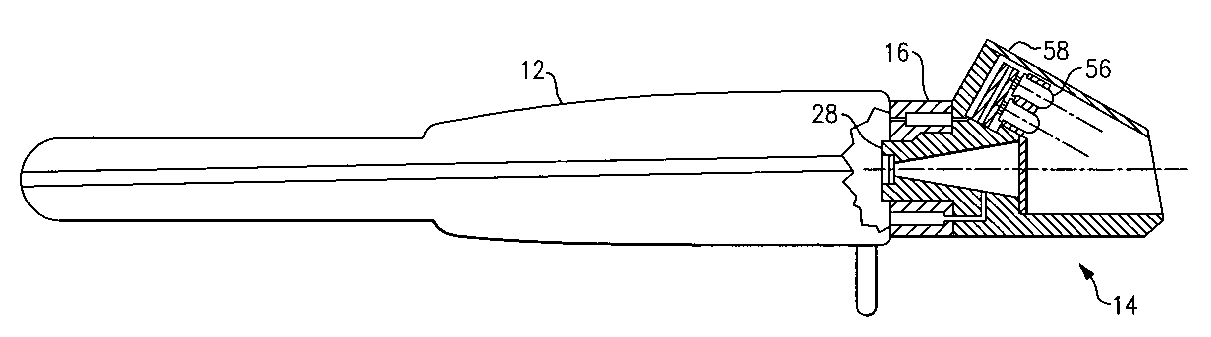
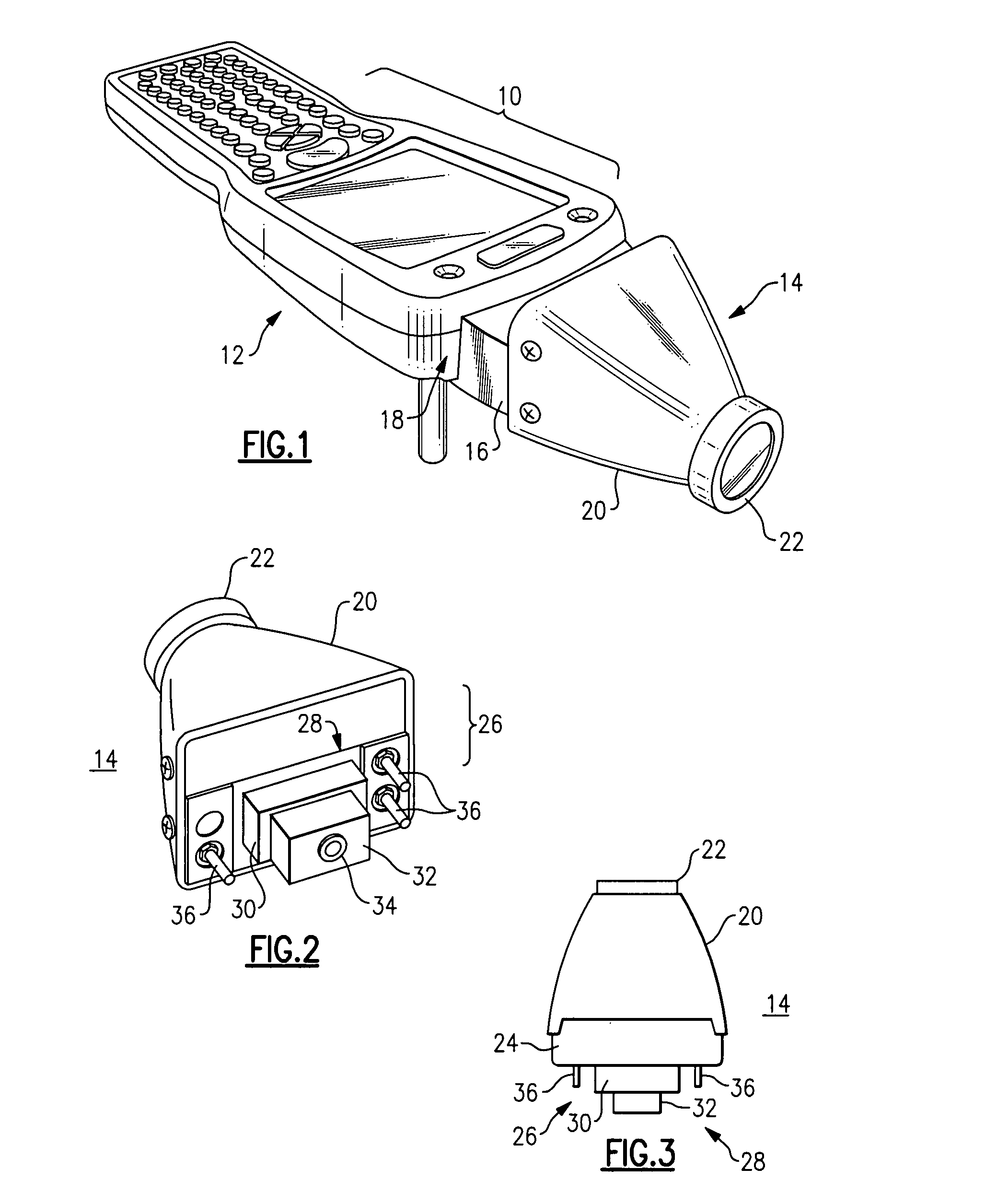
[0032]With reference to the Drawing, and initially to FIG. 1, an optical symbol scanner assembly 10 combines a hand-held data inputting scanner 12, i.e., a hand-held two dimensional bar code scanner, with an interchangeable illumination attachment 14. In this embodiment, the illumination attachment 14 is in the form of a generally pyramidal shaped nosepiece. Here, the scanner 12 is a self-contained battery operated unit, with a display for showing the contents of a bar coded symbol, and keys for inputting data. In other embodiments, the scanner can be wirelessly connected with a central computer, or the scanner can be connected via a cable to remote computer.

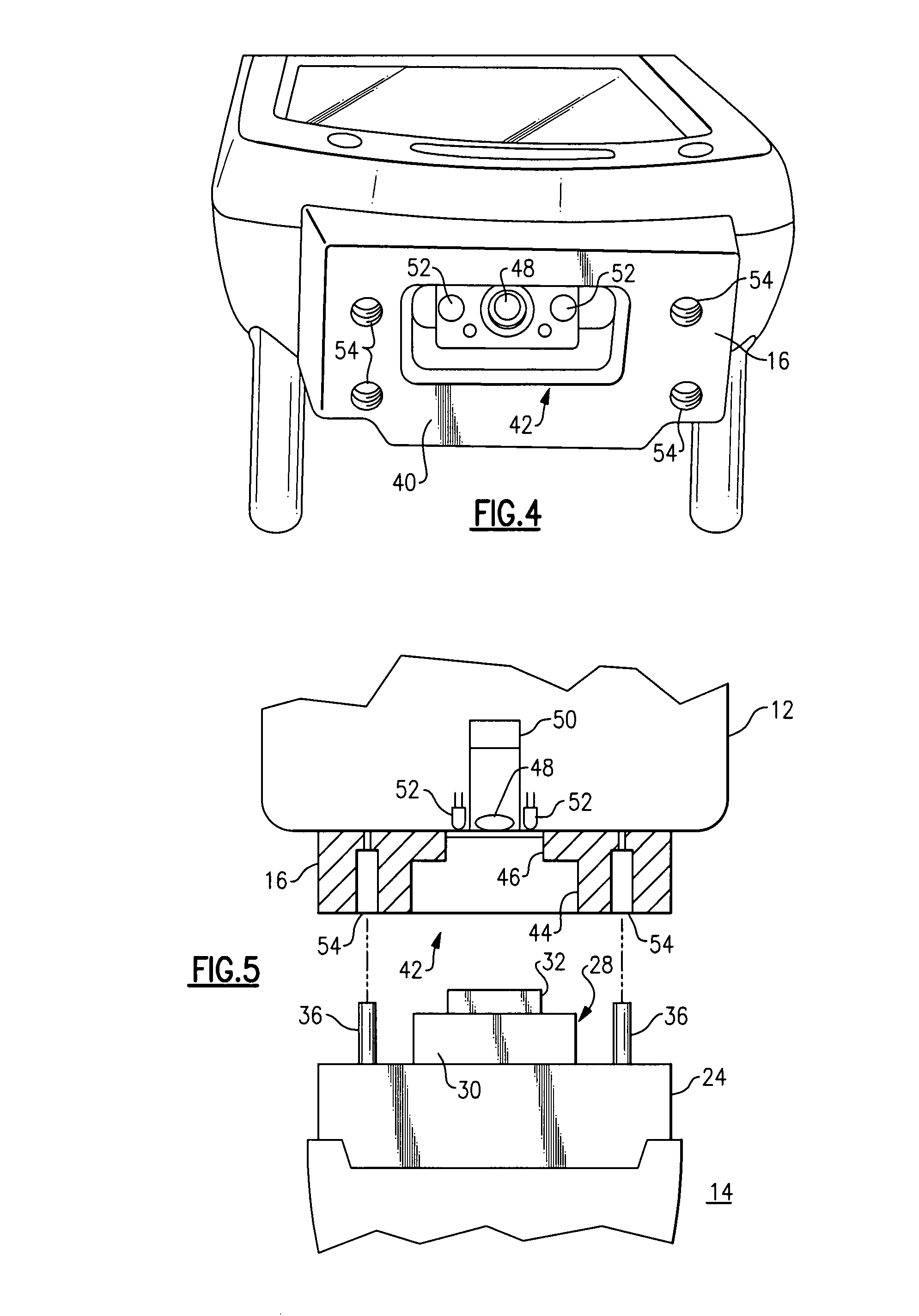
[0033]A socket member 16 is affixed onto a front or distal face 18 of the body of the scanner 12. The interchangeable illuminator attachment 14 plugs in to this socket member 16 as described below. The attachment 14 has an outer shroud 20 that narrows towards its distal end, with an optional front lens or optional transparent c...


PUM


Abstract

A hand-held, compact fixed mounted or mobile optical symbol scanner assembly has a powered socket into which an active or passive illumination module can be installed. The socket has a recess centered at the optic axis, and the illumination attachment module has a male projection that plugs into this recess. Probe type electrodes on the attachment module fit into female socket electrodes on the socket member, so that power can be derived from the scanner for LEDs in the module. The module may convert the voltage to a level suitable for higher wavelengths, and may provide added control of the external LEDs to extend battery life.

Description

BACKGROUND OF THE INVENTION [0001]This invention is directed to optical scanning devices, such as bar code scanners, and is more particularly concerned with an arrangement for adapting the device for reading difficult optical symbols, e.g., small linear or two-dimensional symbols directly marked on articles, or for reading luminescent bar codes that require special black light wavelengths. The invention is more particularly concerned with a combination of a hand-held optical scanner and an illuminator that can be plugged into the scanner, i.e., removably installed so the scanner may be employed either with an illuminator attachment for reading a variety of difficult bar codes or special bar coded symbols, or without the attachment for reading normal bar codes. The device may be a hand-held scanner, either cordless or corded, or the scanner may be built into a data terminal or may be of a compact, fixed mount style.[0002]Within the past several years, two-dimensional bar code systems...

Claims


Application Information

Patent Timeline
Patent Type & Authority Applications(United States)
IPC IPC(8): G06K7/10
CPCG06K7/1098G06K7/10881
Inventor HATTERSLEY, JOHN R.BLACKWELL, FRANCIS O.
Owner INDAL DATA ENTRY AUTOMATION SYST
Why Eureka
Try Eureka