
Safety line anchor

Inactive Publication Date: 2008-01-10
LATCHWAYS PLC (GB)
View PDF9 Cites 18 Cited by
  • Summary
  • Abstract
  • Description
  • Claims
  • Application Information

AI Technical Summary

Benefits of technology

[0010] The invention is a fall arrest bottom anchor assembly for use with a substantially vertically-oriented elongate safety line. The bottom anchor assembly includes a safety line gripper, a safety line tensioner, and a bracket that is adapted to be fixedly mounted. The gripper includes a manually adjustable clamp that can be clamped to the safety line at an adjustable position along its length. The tensioner includes a hollow shaft connected to the gripper. The hollow shaft is adapted to receive the safety line with the safety line extending therethrough and extending both upwardly and downwardly therefrom, and the hollow shaft extends vertically through the fixed bracket downwardly and upwardly from the fixed bracket. The hollow shaft has an externally screw-threaded portion. A load setter of the anchor assembly is threadingly adjustable on the s

Problems solved by technology

These structures are purposely built to be low maintenance and, because many of them stand in remote locations, they may require inspection only once every ten years, perhaps longer.

Method used


Image

  • Safety line anchor
  • Safety line anchor
  • Safety line anchor

Examples


Embodiment Construction

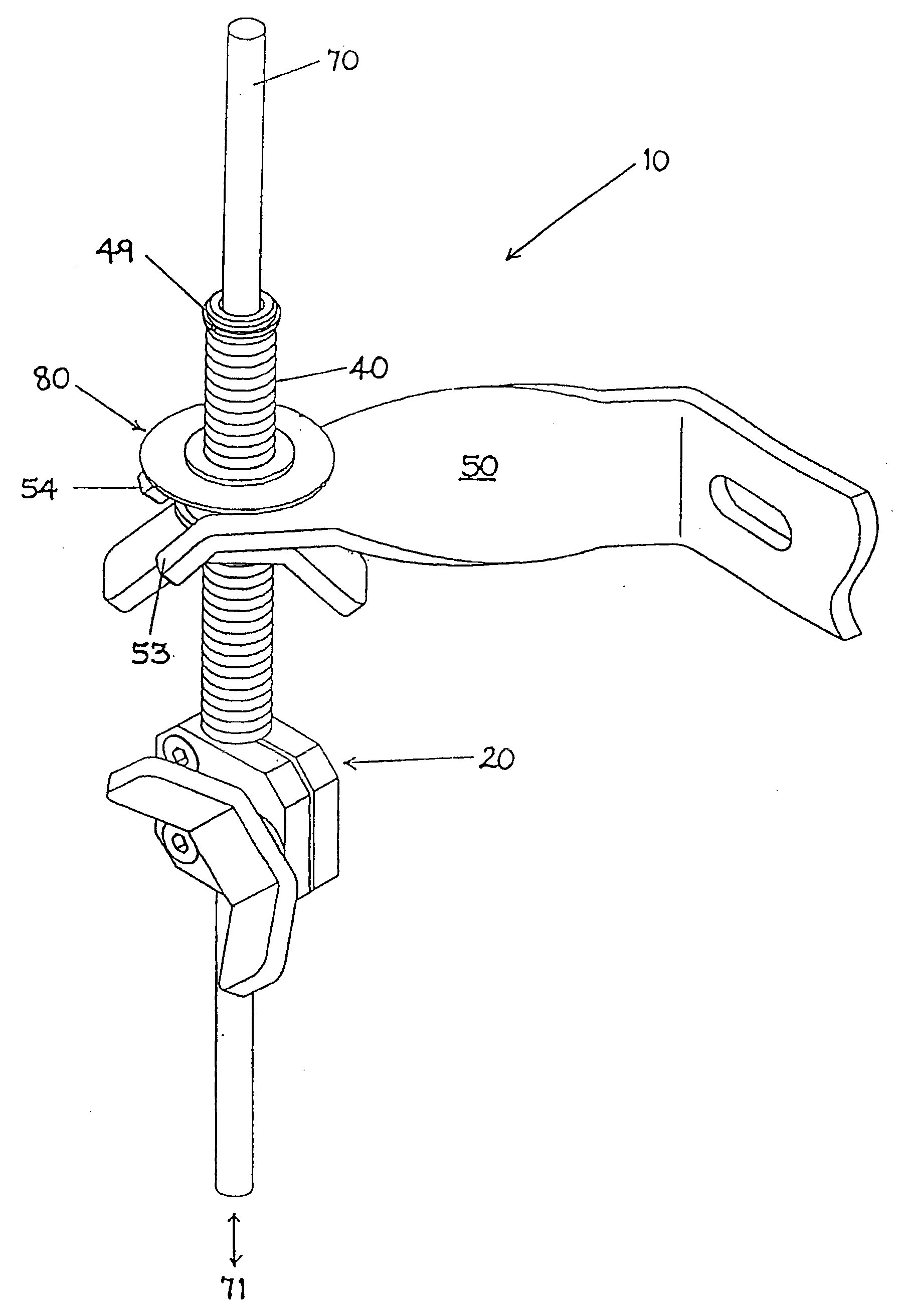
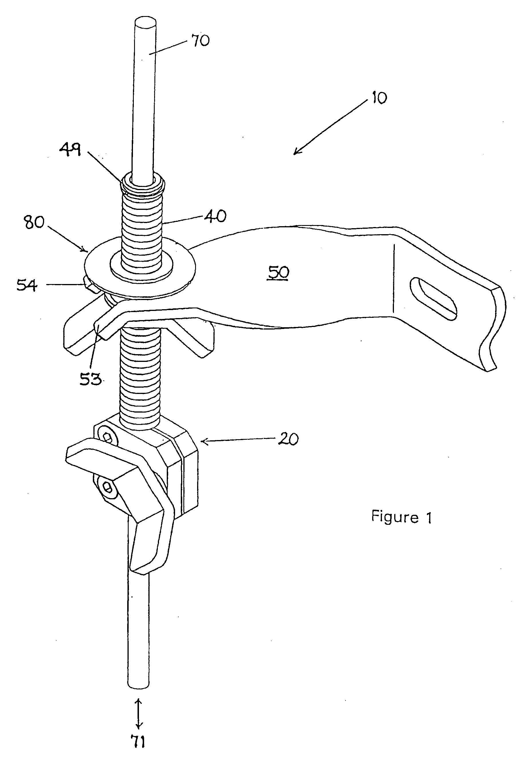
[0027] Referring firstly to FIG. 1, there is shown a perspective view of a bottom anchor assembly 10 attached to a safety line 70 in the form of a multi-stranded metal cable. Typically, the cable diameter for a vertical fall arrest system is 8 mm.

[0028] The bottom anchor assembly consists of a bottom-mounted clamp 20, an externally screw-threaded hollow shaft 40 projecting upwardly from an upper surface of the clamp 20, a bracket 50 for attaching the anchor assembly to the lower portion of a tall structure such as an electricity pylon (not shown) and a load-setting device 80 a portion of which is adapted to bear against the underside of the jaws of the bracket 50. The hollow shaft 40 may include a circlip 49 at its upper end for ensuring that the load-setting device, once installed on the hollow shaft 40, does not become inadvertently lost.

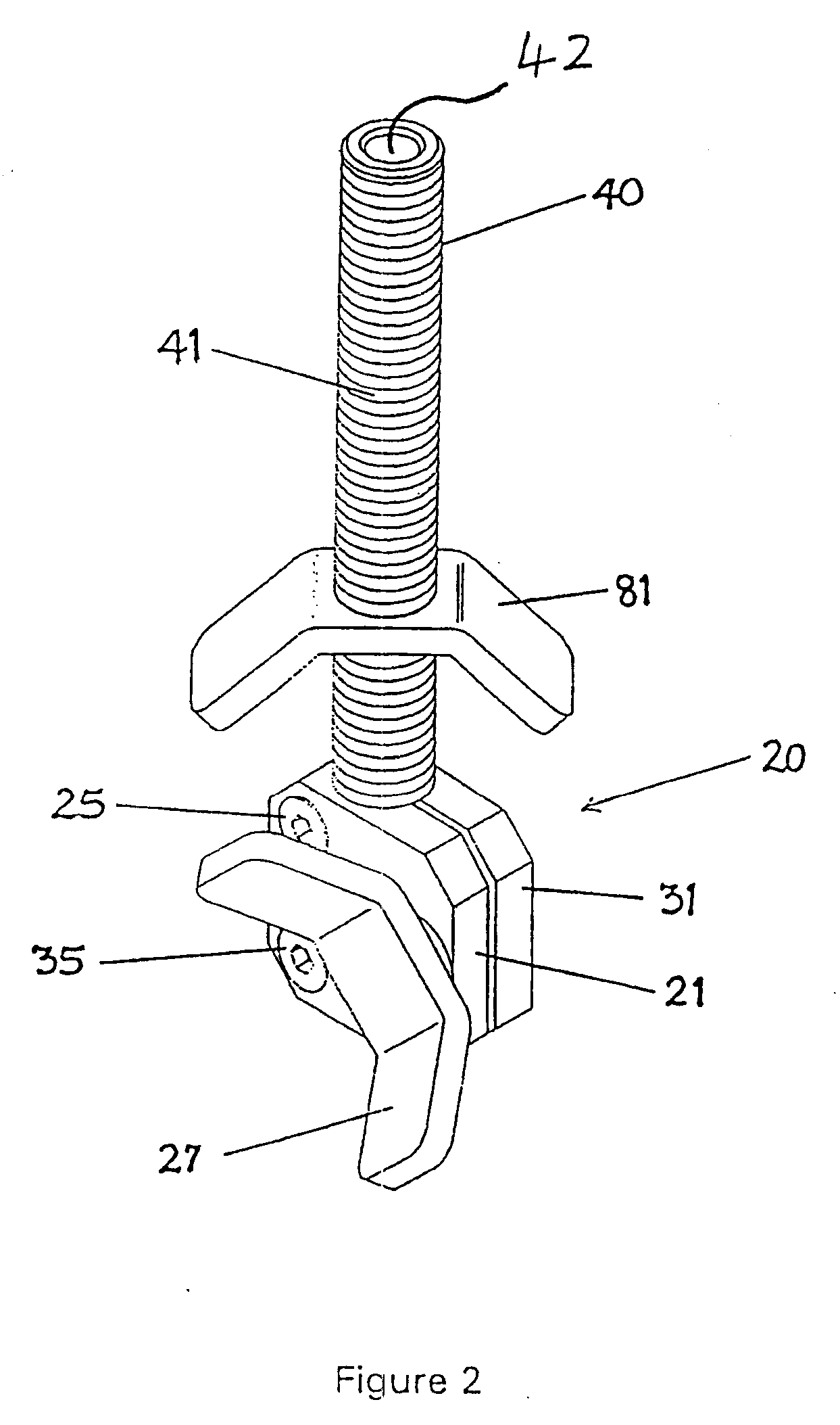
[0029] Referring now to FIGS. 2 and 3, the clamp 20 comprises a pair of clamp blocks 21, 31 adapted to be butted together in face-to-face oppos...


PUM


Abstract

A bottom anchor assembly (10) for a substantially vertically-oriented elongate safety line (70) comprises safety line gripping means (20), safety line tensioning means (80) and a bracket (50). The gripping means (20) includes a manually adjustable clamp (20) and the tensioning means (80) includes a hollow shaft (40) through which the safety line (70) passes. The hollow shaft (40) is externally screw-threaded and carries the load-setting means (80) on its screw-threaded portion (41). The load-setting means (80) is adapted to bear against the underside of the bracket (50) for adjusting the safety line tension to a predetermined value.

Description

CROSS-REFERENCE TO RELATED APPLICATIONS [0001] This application is a continuation of application Ser. No. 09 / 890,771 submitted on Mar. 5, 2002 by Peter Robert Flux with the title SAFETY LINE ANCHOR under 35 U.S.C. 371 from Patent Cooperation Treaty Application PCT / GB00 / 00371 which was filed on Feb. 8, 2000.BACKGROUND OF THE INVENTION [0002] 1. Field of the Invention [0003] The present invention relates to height safety equipment and, in particular, to an anchoring arrangement suitable for anchoring the lower end of a temporary installation of a flexible elongate safety line disposed in a substantially vertical orientation on a tall structure. [0004] 2. Background Art [0005] Tall structures such as electricity pylons and radio or satellite communication masts are periodically inspected to determine whether any maintenance work is required. These structures are purposely built to be low maintenance and, because many of them stand in remote locations, they may require inspection only o...

Claims


Application Information

Patent Timeline
IPC IPC(8): A62B1/04E04G21/32
CPCA62B35/005E04G21/3261A62B35/0068E04G21/3276
Inventor FLUX, PETER ROBERT
Owner LATCHWAYS PLC (GB)
Learn More