Method of forming single-layer coils

a technology of single-layer coils and coils, applied in the direction of electromagnets, dynamo-electric machines, electrical apparatus, etc., can solve the problems of time-consuming and costly coil formation, and achieve the effect of quick, easy and cheap

Inactive Publication Date: 2008-01-17
GE POWER CONVERSION
View PDF8 Cites 21 Cited by
  • Summary
  • Abstract
  • Description
  • Claims
  • Application Information

AI Technical Summary

Benefits of technology

[0006] The present invention aims to provide a quicker, easier and cheaper method of forming a single-layer coil for an electrical machine in a single process from a length of conductor by winding the conductor around first and second coil-forming members provided on a beam having a longitudinal axis and which is capable of being rotated about a first axis of rotation that is substantially parallel to the longitudinal axis of the beam and a second axis of rotation that is substantially at right angles to the longitudinal axis of the beam.

Problems solved by technology

The coils are therefore both time-consuming and costly to form.

Method used


Image

  • Method of forming single-layer coils
  • Method of forming single-layer coils
  • Method of forming single-layer coils

Examples


Embodiment Construction

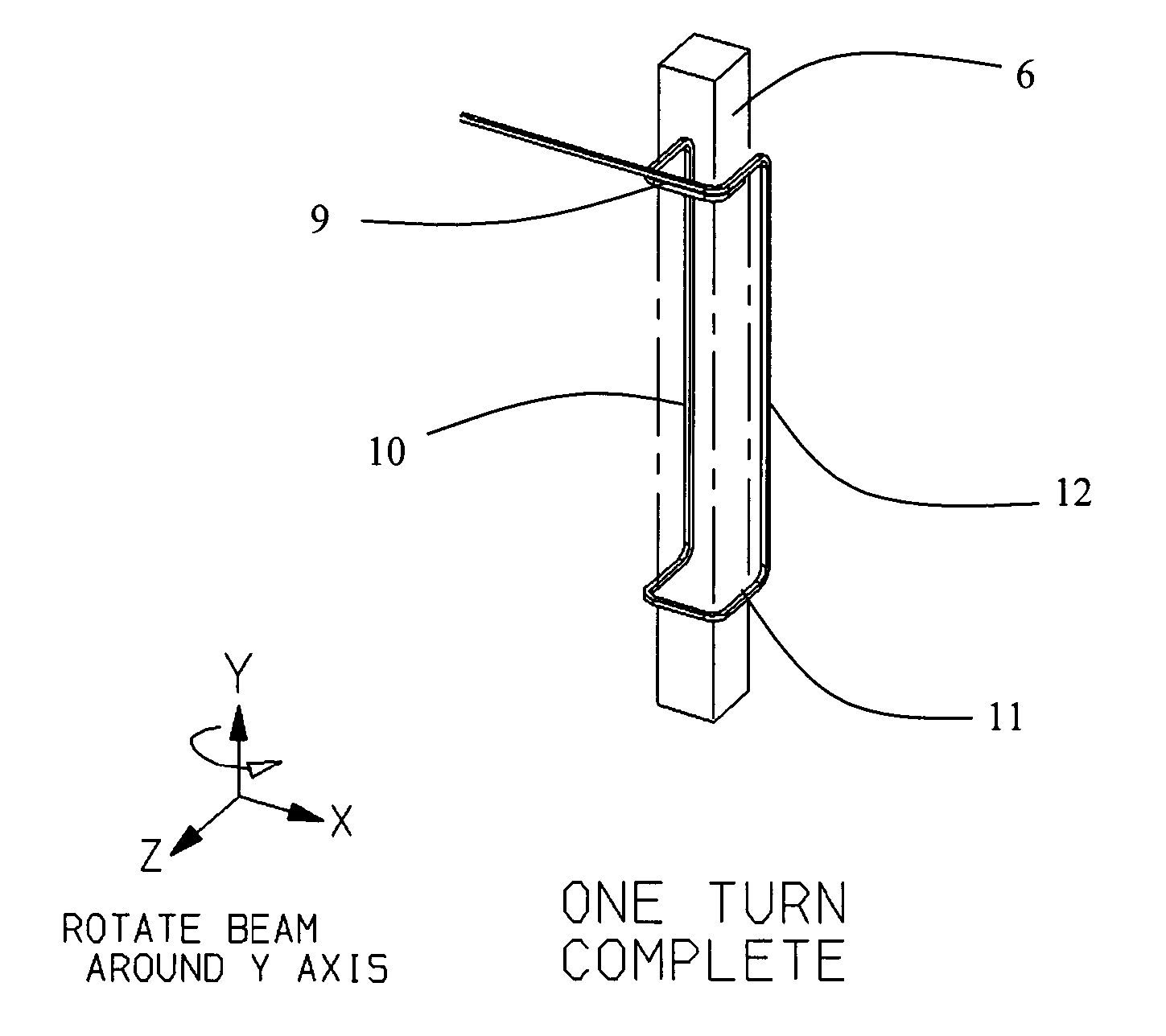
[0033] With reference to FIG. 3 an apparatus for forming a single-layer coil includes a beam 6 that is mounted on bearings for rotation about its longitudinal axis by rotary actuators 3. Any suitable rotary actuator or motor (electric, pneumatic, hydraulic etc.) can be used. The beam 6 can be rotated in both senses as shown by the double-headed arrow labelled “beam rotation”. The rotary actuators 3 or the motors form part of a supporting structure for the beam 6 and are mounted on a turntable 8. The turntable 8 is mounted for rotation about an axis that is at right angles to the longitudinal axis of the beam 6. The turntable 8 can be rotated by a rotary actuator or a motor (not shown).

[0034] The turns of the conductor are wound around a pair of spaced-apart coil-forming members 5 and 7 that form part of the beam 6. The size and shape of the coil-forming members 5 and 7, and their spacing in the direction parallel to the longitudinal axis of the beam 6, will depend on the desired co...


PUM

PropertyMeasurementUnit
angleaaaaaaaaaa
pitch angleaaaaaaaaaa
lengthaaaaaaaaaa

Abstract

The present invention provides a method of forming a single-layer coil for an electrical machine in a single process from a length of insulated rectangular conductor such as copper tape, for example. The coil is formed by winding the conductor around first and second coil-forming members 5 and 7 provided on a beam 6 having a longitudinal axis and which is capable of being rotated about a first axis of rotation that is substantially parallel to the longitudinal axis of the beam and a second axis of rotation that is substantially at right angles to the longitudinal axis of the beam.

Description

FIELD OF THE INVENTION [0001] The invention relates to a method of forming single-layer coils comprising substantially rectangular cross-section insulated conductors, and in particular stator coils, in a single operation. The coils can be used in physically large electrical machines. BACKGROUND OF THE INVENTION [0002] In physically large electrical machines it is quite common to use two-layer coils (also known as “diamond” or “pulled diamond” coils). However, in physically large low-speed electrical machines with a low number of slots-per-pole-per-phase it can be cheaper to use single-layer coils (also known as “concentric” coils). An example of a conventional single-layer coil is shown in FIG. 1. The coil is formed from one or more insulated conductors as a complete loop and has several turns. The coil is received in slots provided in a surface of a stator and includes axially-extending runs 13 that are received within the slots and endwindings 14 that protrude out of the ends of t...

Claims


Application Information

Patent Timeline
Patent Type & Authority Applications(United States)
IPC IPC(8): H01F7/06
CPCH01F41/065Y10T29/49071H02K15/045H01F2041/0662H01F41/071H01F2041/0711B65H54/02H02K15/04H02K3/28
Inventor CLARK, PAUL EATON
Owner GE POWER CONVERSION
Why Eureka
Try Eureka